This thread has been locked.

If you have a related question, please click the "Ask a related question" button in the top right corner. The newly created question will be automatically linked to this question.

AM6442: Linux u-boot and kernel clock configuration for OSPI driver

Part Number: AM6442

Hi,

we are using the latest Linux SDK with the AM6442 and have a customer HW which is using a QSPI flash. Looking at the device trees the max clock is configured for 40MHz in the customer code. The driver somehow makes an assumption that the OSPI HW module receives an internal clock of 200MHz, and the driver configures a /6 divider for the OSPI_CLK, which should now be 33.3MHz

However when looking at the scope the OSPI_CLK is actually 27.6MHz.

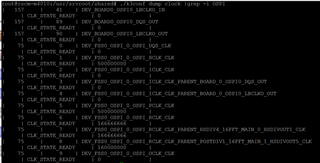
We determine that the internal clock to the OSPI HW module is actually 166.66MHz and not 200MHz, and validate that with the k3_conf utility.

Two questions:

[] Where is the input clock to the OSPI module defined? Is that a u-boot device tree entry or somewhere else?

[] Why is the u-boot and kernel driver assuming that the OSPI module receives a 200MHz clock?

Thanks!

--Gunter

  • Hey Gunter,

    Thank you for your question, my name is Andrew and I would be happy to assist with this.  I have relayed your question to the team and hope to have a response for you within the next 1-2 business days.  While I look into this, has there been any updates/developments to this problem on your end that we should take into consideration?

    Best regards,

    Andrew

  • Hey Gunter,

    Thank you for your patience.  For more information on OSPI_CLK you can refer to the AM64x TRM, specifically pages 184-187: https://www.ti.com/lit/ds/symlink/am6442.pdf?ts=1623989396311&ref_url=https%253A%252F%252Fwww.google.com%252F

    For more detailed information on the QSPI/OSPI flashing process for AM64x, you can refer to the following documentation: https://software-dl.ti.com/processor-sdk-linux/esd/AM64X/07_03_01_006/exports/docs/linux/Foundational_Components/U-Boot/UG-QSPI.html

    For General information on the AM64x boot processes: /cfs-file/__key/communityserver-discussions-components-files/791/AM64x_5F00_Boot_5F00_Overview.pdf

    Do any of these help clarify the issue you are encountering?

    Best regards,

    Andrew

  • Hi Andrew,

    actually the question is a very specific software question as well as a Linux driver behavior question. We believe there is a bug in the driver, that is it is assuming the wrong input clock and making decisions based on that. The questions are to get to the bottom of that.

    Regards,

    --Gunter

  • Hi,

    do you have an update on this thread?

    Thanks!

    --Gunter

  • Hey Gunter,

    Thank you for your patience and I apologize for the delay.  Would you mind posting the exact output you received from the k3conf utility? Also, could you provide your scope capture of "OSPI_CLK"?

    Best regards,

    Andrew

  • Hey Gunter,

    Could you provide us an update as to if you are still encountering this issue?

    Best regards,

    Andrew

  • Hi Andrew,

    yes, the issue remains, as it is I believe a Linux clock driver issue, where the driver assumes a different source clock to work from to determine multiplier and divider for the SPI clock. The driver assumes the source clock is 200MHz while the actual clock is 166MHz.

    Here is the k3conf output:

    Regards,

    --Gunter

  • Hi Andrew,

    see again my original questions in that regard:

    Two questions:

    [] Where is the input clock to the OSPI module defined? Is that a u-boot device tree entry or somewhere else?

    [] Why is the u-boot and kernel driver assuming that the OSPI module receives a 200MHz clock?

    Regards,

    --Gunter

  • Hey Gunter,

    Thank you for the additional information, I have relayed your observations to the team and hope to have an update from them shortly.

    Best regards,

    Andrew

  • Hey Gunter,

    Thank you for your patience.  I actually found another E2E thread for AM64x, on a related topic, that details the process in which OSPI0_CLK attributes are accessed and set: https://e2e.ti.com/support/processors-group/processors/f/processors-forum/1096598/am6442-ospi_ecc-interrupts

    I have also quoted the relevant code section to look for in the dts file below:

    Fullscreen
    1
    2
    3
    4
    5
    6
    7
    8
    9
    10
    11
    12
    13
    14
    15
    ospi0_pins_default: ospi0-pins-default {
    pinctrl-single,pins = <
    AM64X_IOPAD(0x0000, PIN_OUTPUT, 0) /* (N20) OSPI0_CLK */
    AM64X_IOPAD(0x002c, PIN_OUTPUT, 0) /* (L19) OSPI0_CSn0 */
    AM64X_IOPAD(0x000c, PIN_INPUT, 0) /* (M19) OSPI0_D0 */
    AM64X_IOPAD(0x0010, PIN_INPUT, 0) /* (M18) OSPI0_D1 */
    AM64X_IOPAD(0x0014, PIN_INPUT, 0) /* (M20) OSPI0_D2 */
    AM64X_IOPAD(0x0018, PIN_INPUT, 0) /* (M21) OSPI0_D3 */
    AM64X_IOPAD(0x001c, PIN_INPUT, 0) /* (P21) OSPI0_D4 */
    AM64X_IOPAD(0x0020, PIN_INPUT, 0) /* (P20) OSPI0_D5 */
    AM64X_IOPAD(0x0024, PIN_INPUT, 0) /* (N18) OSPI0_D6 */
    AM64X_IOPAD(0x0028, PIN_INPUT, 0) /* (M17) OSPI0_D7 */
    AM64X_IOPAD(0x0008, PIN_INPUT, 0) /* (N19) OSPI0_DQS */
    >;
    };
    XXXXXXXXXXXXXXXXXXXXXXXXXXXXXXXXXXXXXXXXXXXXXXXXXX

    Please let us know if this helps, or if you require further assistance.

    Best regards,

    Andrew

  • Hi Gunter,

    Sorry for the delay.

    The driver somehow makes an assumption that the OSPI HW module receives an internal clock of 200MHz, and the driver configures a /6 divider for the OSPI_CLK, which should now be 33.3MHz

    Can you please point to the code where the driver assumes the OSPI input clock is 200MHz? and where the driver configures the /6 divider? Or how do you determined this information?

  • Hi Bin,

    we see the /6 divider by the fact that k3conf shows that the actual OSPI internal clock is 166MHz (not 200MHz), and we see the OSPI interface clock on the scope at 27.6MHz (166MHz/6).

    Regards,

    --Gunter

  • Hi Gunter,

    The kernel DTS sets OSPI input clock to be 166MHz, and the max output clock to be 40MHz. So the divider should be /6, which yields the output clock as 27.6MHz. Divider /4 would make the output clock as 41.5MHz which exceeds the max 40MHz setting.

  • Hi Bin,

    I will ask the customer to test that theory, by setting the ospi output clock to 45MHz and then test the ospi clock speed with a scope.

    [1] if the driver assumes 166MHz input clock (we think it does):

    ospi output clock configured in dts to 45MHz, and then seeing if the driver configures a Divider /4.

    It should do that based on the calculation 166MHz/4 = 41.5MHz, which is the highest possible clock, but lower than 45MHz.

    [2] if the driver assumes 200MHz input clock:

    At the same time we want to test here that the driver is NOT assuming erroneously a 200MHz input clock. If the driver happens to assume 200MHz input clock, then it should configure to divider /6, leading to 33MHz. This is the highest possible clock, lower than 45MHz. It should not configure to divider /4, as that would lead to 50MHz output clock, higher than 45MHz.

    Regards,

    --Gunter