This thread has been locked.

If you have a related question, please click the "Ask a related question" button in the top right corner. The newly created question will be automatically linked to this question.

AM4378: GPMC's a1 port cannot be set to C5 pin

Part Number: AM4378
Other Parts Discussed in Thread: SYSCONFIG

Hi experts,

My customer wants to set GPMC's a1 port to C5 pin.

My customer wants to set GPMC's a1 port to C5 pin. However, when the a1 port is set to the C5 pin using the Sysconfig tool, the D8 pin of the a27 port conflicts as shown in the figure below. Since I have not set any ports other than GPMC, there is no port that conflicts with the D8 pin. However, this setting will result in a conflict error. Why is this error printed?

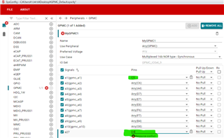
Attach the .syscfg file for this configuration:GMPC_custom.zip

If they set the GPMC's a1 port to the A21 pin, no error will be printed as below.

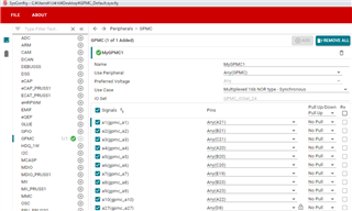
Attach the .syscfg file for this configuration:GPMC_Default.zip

The sysconfig tool version is "sysconfig_1.14.0"

Best regards,
Sasaki

  • Sasaki

    There are IO set restrictions that must be honored when configuring a peripheral.   The GPMC interface has a large number of validated configurations that can be used.  However, by selecting a specific pin for a signal, you lock-in the signal assignment and the tool cannot move it thus restricting the options available. While this is a valid use of the tool, it does limit the ability of the tool to try and find a valid solution to a system configuration. 

    in this case there are 4 signals locked to pins. 

    CSN3 -> B12
    DIR -> A3
    A27 -> D8
    A1 -> C5

    The error is shown because this combination of pins does not appear in any IOSet and therefore cannot be used. 

    I there a particular need for these signals to be on these pins?  If not, then do not lock the signals and let the tool adjust as needed.  You may find as more interfaces are added, the GPMC implementation may change.  

    Once the use case is selected, uncheck any conflicts that may exist on signals not needed.   

    --Paul 

  • Hi Paul-san,

    Thank you for your information.

    I there a particular need for these signals to be on these pins? 

    The customer has designed a board with these signals (A27 -> D8,  A1 -> C5) on these pins. Therefore, They would like to proceed with the design with this pin arrangement.
    Is it possible to design with this pinout?
    If it is not possible, I will ask the customer to modify the board.

    Regards,
    Sasaki

  • Only error free signal/pin combinations are timing validated.  Any other combinations may have timing issues. 

    --Paul  

  • Paul-san,

    Thank you for your information.

    I got it.

    Best regards,
    Sasaki