This thread has been locked.

If you have a related question, please click the "Ask a related question" button in the top right corner. The newly created question will be automatically linked to this question.

AM4377: QSPI-Flash for AM4377 / Uniflash CLI

Part Number: AM4377
Other Parts Discussed in Thread: UNIFLASH, , DP83848K

Hello,

I work on the same projekt mentioned in AM4377: QSPI-Flash for AM4377 and we still have the problem that sometimes the board doesn't boot.

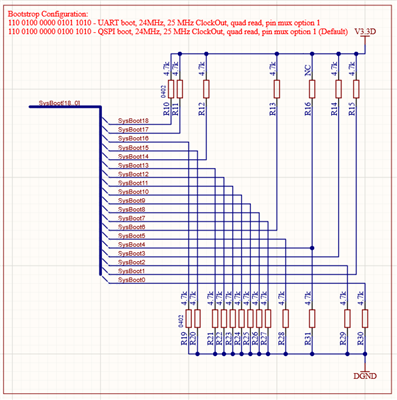
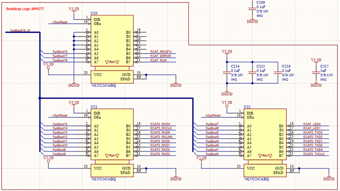
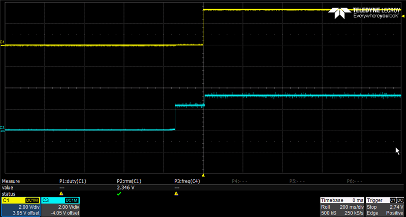
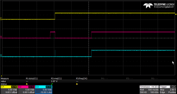
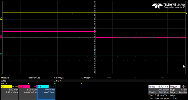
I have measured DCLK and nCS of the QSPI when the boot process fails and the communication doesn't even start even though the SYSBOOT configuration being in QSPI (110'0100'0000'0100'1010) mode.

Is there any way to make sure we are in the correct boot mode?

Maybe it's a hardware problem, because some boards work perfectly, while others get the error about every other time. I was able to reproduce the fault with a "bad" board consistently with power cycling the device when it's on with about 0.5s off time. If the device is turned off for longer than about a second it boots without any problems. In both cases the power sequencing is the same. I think this is an argument against a hardware fault.

A maybe related problem i discovered:

The following problems are just happening with the "bad" boards which are around 20%. With the others the programming with the UniFlash is successful.

When programming the flash memory via the UniFlash CLI, after loading the .out file with the USB560v2 System Trace over JTAG, there is no output of "C" on the COM-port despite the return value beeing succesful.

CMD line instruction:

.\dslite.bat --mode load --config=PATH\TargetConfig\sqpAM437x.ccxml -f PATH\ProgFiles\uart_sqpAM437x_flash_programmer.out -n 1

Output:

> "C:\TI\uniflash_8.1.1\deskdb\content\TICloudAgent\win\ccs_base\DebugServer\bin\DSLite" load --config=PATH\TargetConfig\sqpAM437x.ccxml -f PATH\ProgFiles\uart_sqpAM437x_flash_programmer.out -n 1

For more details and examples, please refer to the UniFlash Quick Start guide.

DSLite version 12.2.0.2919
Configuring Debugger (may take a few minutes on first launch)...
        Initializing Register Database...
        Initializing: IcePick_D_0
Loaded FPGA Image: C:\TI\uniflash_8.1.1\deskdb\content\TICloudAgent\win\ccs_base\common\uscif\dtc_top.jbc
        Executing Startup Scripts: IcePick_D_0
        Initializing: CS_DAP_M3
        Executing Startup Scripts: CS_DAP_M3
        Initializing: M3_wakeupSS_1
        Executing Startup Scripts: M3_wakeupSS_1
        Initializing: CS_DAP_DebugSS
        Executing Startup Scripts: CS_DAP_DebugSS
        Initializing: CortexA9
        Executing Startup Scripts: CortexA9
        Initializing: CSSTM_0
        Executing Startup Scripts: CSSTM_0
        Initializing: CSETB_0
        Executing Startup Scripts: CSETB_0
        Initializing: PRU_ICSS1_PRU0
        Executing Startup Scripts: PRU_ICSS1_PRU0
        Initializing: PRU_ICSS1_PRU1
        Executing Startup Scripts: PRU_ICSS1_PRU1
        Initializing: PRU_ICSS0_PRU0
        Executing Startup Scripts: PRU_ICSS0_PRU0
        Initializing: PRU_ICSS0_PRU1
        Executing Startup Scripts: PRU_ICSS0_PRU1
Connecting...
GEL: CortexA9: Output: ****  AM437x SQP Initialization is in progress ..........
GEL: CortexA9: Output:  **** Device Type: GP
GEL: CortexA9: GEL Output: System input clock is 24MHz
GEL: CortexA9: GEL Output: ****  AM43xx NITRO (1000MHz) with CLKIN=24MHz is in progress .........
GEL: CortexA9: GEL Output:       ****  Going to Bypass...
GEL: CortexA9: GEL Output:       ****  Bypassed, changing values...
GEL: CortexA9: Output:   ****  Locking PLL
GEL: CortexA9: GEL Output:       ****  MPU PLL locked
GEL: CortexA9: GEL Output:       ****  Core Bypassed
GEL: CortexA9: GEL Output:       ****  Now locking Core...
GEL: CortexA9: GEL Output:       ****  Core locked
GEL: CortexA9: GEL Output:       ****  Calculated PER SD Divisor=4
GEL: CortexA9: GEL Output:       ****  PER DPLL Bypassed
GEL: CortexA9: GEL Output:       ****  PER DPLL Locked
GEL: CortexA9: GEL Output:       ****  Calculated EXTDEV SD Divisor=2
GEL: CortexA9: GEL Output:       ****  EXTDEV DPLL Bypassed
GEL: CortexA9: GEL Output:       ****  EXTDEV DPLL Locked
GEL: CortexA9: GEL Output:       ****  DISP PLL Config is in progress ..........
GEL: CortexA9: GEL Output:       ****  DISP PLL Locked
GEL: CortexA9: GEL Output:       ****  DDR DPLL Bypassed
GEL: CortexA9: GEL Output:       ****  DDR DPLL Locked
GEL: CortexA9: GEL Output: ****  Setting DDR3  = 400MHz
GEL: CortexA9: GEL Output: ****  AM43xx NITRO configuration is done .........
GEL: CortexA9: GEL Output: Starting DDR3 configuration...
GEL: CortexA9: Output: EMIF PRCM is in progress .......
GEL: CortexA9: Output: EMIF PRCM Done
GEL: CortexA9: GEL Output: EMIF CLK enabled...
GEL: CortexA9: GEL Output: Waiting for VTP Ready .......
GEL: CortexA9: GEL Output: VTP is Ready!
GEL: CortexA9: GEL Output: VTP controller enabled
GEL: CortexA9: GEL Output: Checking if DLL is ready...
GEL: CortexA9: GEL Output: DLL is ready
GEL: CortexA9: GEL Output: Configuring DDR IOs and Control Module registers...
GEL: CortexA9: GEL Output: Configuration of Control Module registers complete
GEL: CortexA9: GEL Output: Setting up DDR3 H/W leveling configuration...
GEL: CortexA9: GEL Output: Starting EMIF controller configuration...
GEL: CortexA9: GEL Output: EMIF Config for SQP
GEL: CortexA9: GEL Output:

DDR3 Hardware leveling complete... Outputing all the leveling results !!!

GEL: CortexA9: GEL Output: PHY_STATUS_12=0x07000099
GEL: CortexA9: GEL Output: PHY_STATUS_13=0x070000A0
GEL: CortexA9: GEL Output: PHY_STATUS_14=0x070000B4
GEL: CortexA9: GEL Output: PHY_STATUS_15=0x070000AD
GEL: CortexA9: GEL Output: PHY_STATUS_16=0x00000000
GEL: CortexA9: GEL Output: PHY_STATUS_7 =0x00000046
GEL: CortexA9: GEL Output: PHY_STATUS_8 =0x00000044
GEL: CortexA9: GEL Output: PHY_STATUS_9 =0x00000046
GEL: CortexA9: GEL Output: PHY_STATUS_10=0x00000044
GEL: CortexA9: GEL Output: PHY_STATUS_11=0x00000000
GEL: CortexA9: GEL Output: PHY_STATUS_17=0x012700D1
GEL: CortexA9: GEL Output: PHY_STATUS_18=0x000000CD
GEL: CortexA9: GEL Output: PHY_STATUS_19=0x019300E0
GEL: CortexA9: GEL Output: PHY_STATUS_20=0x010300DF
GEL: CortexA9: GEL Output: PHY_STATUS_21=0x00000000
GEL: CortexA9: GEL Output: PHY_STATUS_22=0x00E70091
GEL: CortexA9: GEL Output: PHY_STATUS_23=0x03C0008D
GEL: CortexA9: GEL Output: PHY_STATUS_24=0x015300A0
GEL: CortexA9: GEL Output: PHY_STATUS_25=0x00C3009F
GEL: CortexA9: GEL Output: PHY_STATUS_26=0x00000000
GEL: CortexA9: GEL Output:

DDR3 configuration is complete!!!

GEL: CortexA9: GEL Output: Turning on EDMA...
GEL: CortexA9: GEL Output: EDMA is turned on...
GEL: CortexA9: Output: ****  AM437x IDK EVM Initialization is Done ******************


GEL: CortexA9: Output:  **** PRU-ICSS PRCM Enable Step 1 is in progress ****
GEL: CortexA9: Output:  **** PRU-ICSS PRCM Enable Step 1 is Done ****
GEL: CortexA9: Output:  **** PRU-ICSS PRCM Enable Step 2 is in progress ****
GEL: CortexA9: Output:  **** PRU-ICSS PRCM Enable Step 2 is Done ****
Fill Memory
        Verifying 0x54410000
        Filling 0x54417FF0: 99%
        Verifying 0x54417FF0: 99%
        Filling 0x54418000: 100%
Loading Program: PATH\ProgFiles\uart_sqpAM437x_flash_programmer.out
        Preparing ...
        PT_LOAD[0]: 0 of 40084 at 0x40300000
        PT_LOAD[0]: 32752 of 40084 at 0x40300000: 81%
        Finished: 81%
        Setting PC to entry point.: 81%
Running...
Success

When loading the .out-file with the Code Composer Studio (10.4.0.00006) the "C" output on the COM-port is there but most of the times the process fails at 8% when trying to flash the image.

When this happens the QSPI-communication also doesn't start. When i try it this way the loading is succesful 1 out of 10 times.

CMD line instruction:

C:\TI\uniflash_8.1.1>dslite.bat --mode processors -c COM6 -f PATH\ProgFiles\bootloader_boot_qspi_a9host_release.bin -d 2 -o 0

Output:

Executing the following command:
> C:\TI\uniflash_8.1.1\processors\ProcessorSDKSerialFlash.exe -c COM6 -f PATH\ProgFiles\bootloader_boot_qspi_a9host_release.bin -d 2 -o 0

For more details and examples, please refer to the UniFlash Quick Start guide.

The file extension is .bin

----------------------------------------------------------------------------
ProcessorSDKSerialFlash CLI Tool
Copyright (C) 2017-2022 Texas Instruments Incorporated - http://www.ti.com/
Version 1.7.0.0
----------------------------------------------------------------------------
Transferring the Image to Flash Programmer..

Transferring Header Information..
Header Transfer Complete!

Flashing Image of size 37768 bytes
8% complete
Flash Programming Failed!!

When trying to delete the flash memory there is also no communication between flash and am4377 even tough it says Flash Erase Success!

CMD line instruction:

C:\TI\uniflash_8.1.1>dslite.bat --mode processors -c COM6 -d 2 -e 0x200000

Output:

Executing the following command:
> C:\TI\uniflash_8.1.1\processors\ProcessorSDKSerialFlash.exe -c COM6 -d 2 -e 0x200000

For more details and examples, please refer to the UniFlash Quick Start guide.


----------------------------------------------------------------------------
ProcessorSDKSerialFlash CLI Tool
Copyright (C) 2017-2022 Texas Instruments Incorporated - http://www.ti.com/
Version 1.7.0.0
----------------------------------------------------------------------------
Erasing Flash....

Transferring Header information..
Header Transfer Complete!!
Flash Erase Success!

In the Quicik start guide it says with %errorlevel% it's possible to check if the previous operation passed. In my case this is true for the "dslite.bat --mode load ..." command but the "dslite.bat --mode processors ..."  instruction always returns 1 even if everything loads succesful (bootloader and .bin file).

Is this a bug of the batch file or is it sure that something is wrong? And is there any other way to ensure the process is succesful/failed?

Do you have any suggestions on how to proceed?

Regards, Timo

  • Timo, do you see the same behavior as the other e2e post?  The other post mentioned that the boot is successful about every other attempt.  Do the 20% failing boards exhibit this behavior, or do they fail at every boot attempt.

    I looked back at the other post, and we had some debug q and a, I assume the same is true now about the CTRL_STS and Tracing Vectors?

    -are you booting by cycling power to the board?  Do you have the ability to just toggle the reset signal (either POR or warm reset)?  If so, does the board ever fail with just a reset toggle? 

    -How are you performing the quick on/off?  What does the POR input signal look like on a failing attempt?  Do the power supplies ramp completely down then up again during this quick on/off?  Check that the POR reset signal still conforms to the power sequencing diagram in the datasheet when performing the quick on/off.  Especially what is important is the reset signal should be low the entire time the power sequencing (up and down) is occurring.  And it also needs to stay low until the input clock (clk_m_osc) is stable

    Regards,

    James

  • Hi James, thanks for the answer.

    Yes I'm booting by power cycling the board and it really depends on the timing. Like mentioned above, if it's around 0.5s off time it fails every time. But this is just a way for me to reproduce the error on my desk.

    No the CTRL_STS and Tracing Vectors aren't the same:

    - The CTRL_STS and 0x40338E48 change between the shown values, the others stay always the same

    - Ctrl_STS: 0x0600340 or 0x0640036E or 0x0650036C
    - Tracing Vectors
    	0x40338E40	:   0000001E   
    	0x40338E44  :   00000000
    	0x40338E48  :   00000004 or 00000008
    	0x40338E4B  :   00000000
    	0x40338E50  :   00000000

    I can perform a warm reset (with WARMRSTn/Pin G22) and if the boot cycle worked once it always boots fine when warm reseted. But if it didn't boot and I tried to warm reset it never worked.

    The POR reset signal looks the same in both cases: It goes low before all power supplys and up again after ~200ms of the correct power sequencing (clk_m_osc is also stable in both cases).

    Yes, the power supplies completely ramp down.

    Regards,

    Timo

  • Ok, definitely the problem is with the bootmode signals.  Since you are getting varying results in the CTRL_STS register, that means the bootmode being latched by the processor could be different, and thus the boot sequence is different and may not even include QSPI.

    Since you have checked the reset and clock signals, my guess is that the bootmode signals are not given enough time to settle to a valid voltage level since these are controlled by pull resistors.  Furthermore, if you have other components on the bootmode signals (eg, connected to other peripherals), these signals could be loaded by the other devices and may take a while to ramp to valid voltage levels, especially if there are weak pulls on them.  Also if they are connected to other devices, you would have take into consideration the pulls imposed on the IOs of those devices when determining the proper resistance value of the external pull resistor

    You would either have to elongate the POR to give time for the bootmode signals to settle, or put a stronger pull on the boot mode signals so they will settle to a valid voltage faster. 

    Regards,

    James


  • Hi James,

    Thanks for the suggestions, I found the problem.

    The bootstrapping is very similar to that of the AM437x Industrial EVM, but we use TI's DP83848K as the PHY.

    When the bootstrap fails, TXD_0 to TXD_3 of the DP83848K all pull up to 3.3V.
    TXD1 (Sysboot4) and TXD3 (Sysboot2) are also pulled down (with 4.7k resistors) because of the bootstrap configuration. I end up with about 2.2V and thus in the wrong boot mode.

    To be sure, I unsoldered the PHY and from then on it always booted correctly.
    I have no idea why pins TXD_0 to TXD_3 (pin 4-7) are being driven, I don't think that should be possible.

    Is there a way/mode where these pins are driving or must  it be a hardware error?

    Regards,

    Timo

  • Sorry TImo, i'm a bit confused.  What you are describing are the bootstrap pins for the Ethernet PHY (TXD0-3).  I thought you were having a problem with the QSPI boot or the programming of the QSPI using Uniflash.  How is the Ethernet port getting involved here?

    If it is further into your bootloader where you initialize the Ethernet Port, then there are certainly some considerations to ensure the PHY latches its bootstraps correctly.  You must ensure any signals which are connected to the Ethernet PHY bootstrap signals are not driving when the reset to the PHY is de-asserted.  Do you have software control of the PHY reset?

    Regards,

    James   

  • Sorry I see now that my explanation wasn't very clear.

    The problem is still the QSPI boot an the programming with Uniflash.

    Like you suggested I checked if the bootmode is varying an found out that sometimes it's not correct for both the QSPI boot and the programming.

    The Bootstrap config I use:

    These signals go into a tri-state transceiver which switches to high Z after booting.

    nSysReset is the warm reset signal:

    On one side they are routed to the PHY:

    On the other side to the processor:

    I have software control of the PHY reset but I think the problem happens before/while booting.

    I measured the POR signal (C1) and the ECAT0_TXD3 (C3):

    The TXD3 signal should be zero the whole time. The ~150ms where the signal is around 2.2V the resistor R29 pulls down but something is also driving this line. After the warm reset signal goes high, U22 goes into high Z mode and TXD3 goes to 3.3V.

    The TXD1 signal shows the same behavior. With these two signals "high" the bootmode is obviously not correct (NAND_I2C instead of QSPI).

    After removing the PHY (U16) the bootmode is always right and I never measured these half voltages.

    Therefore I think the PHY is interferring with the booting of the processor.

    I don't think that the bootstrap of the PHY has anything to do with this:

    The TXD_# signals aren't needed in the boot mode selecting of the PHY and I'm really confused because in my opinion these pins are just input pins?

     I could just put a stronger pull on the boot mode signals of the AM4377 but that's not a really satisfying solution.

    Do you have a suggestion for the behavior of the DP83848K?

    Thanks very much,

    Timo

  • Can you show me the circuit for PHY_RESETn, or where it is sourced from?  I think what is happening is that the PHY is coming out of reset before or while the sysboot signals are being latched by the processor, and any of its outputs may be conflicting with the sysboot signal level.  So it may not be the TXD signals getting in the way (they shouldn't ,as you say, since they are inputs to the PHY), but some of the other PHY outputs.

    REgards,

    James

  • Here is the schematic:

    I made some measurements

    C1: PORz

    C2: ECAT_RESETn

    C3: PHY_RESETn

    Zoomed in when when ECAT_RESETn goes low for the first time the PHY_RESETn signal is high for around 16us:

    I'm not sure why the ECAT_RESETn is high even before booting, maybe that's the problem?

    Regards,

    Timo

  • Timo, a couple of questons with this new information;

    -the latest schematic shows GPIO2_25 (pin A24) connected to ECAT_RESETn which is pulled down with a 2.2K resistor.  Yet in early schematics you show signal SysBoot18 (which should be connected to the same pin) pulled up with a 4.7K.  So you have the same signal connected to both sides of the 74LVC245 buffer.  I think that is why you are getting the short pulse around the rising edge of reset.  This is not a huge deal with respect to booting, as SysBoot18 just controls a CLKOUT signal (ie, it doesn't not affect boot in any way), but should be fixed as it is affecting the PHY Reset.  

    -Now you need to check some of the other bootmode signals to see if there are similar issues.  For example, C17, D17, D19, (and others) are all bootmode pins which on your board are also connected to the PHY and possibly the SysBootxx signals.  There may be similar unintentional connection as described earlier.  These are most likely causing your variable bootmode latching.  

    -You show a signal nSys_Reset.  What is the source of that signal?  The scope shots you have show appear to be the result of a warm reset.  How are you triggering these reset signals?  With a full power cycle to the board?  Push button toggle of warm reset?  Some other means?

    Regards,

    James

  • Hi James,

    You are right about the connection on both sides, somehow that escaped my attention, thanks.
    There is the same problem with ECAT0_RXER / D19 / Sysboot13 but when i measure it, it always changes from low to high in the correct way after nSysReset goes high.

    Here the schematic of the nSysReset:

    I trigger the reset signal with a full power cycle.

    Regards,

    Timo

  • Hi Timo, 

    i still go back to the fact that you are latching different values into CTRL_STS on different boots, that certainly needs to be corrected.  The boot pins are latched around rising edge of PORz, so those signals have to be in the correct state at that point.  Around that time, the PHY should be in reset, and the transceiver for the sysboot pulls should be enabled (that should be guaranteed by the warm reset signal nSysReset

    One of your scope shots shows a 16us pulse on PHY_RESET, which implies nSysReset is high as well, right around the PORz rise.  This should not be the case as the warm reset output should be extended past PORz by a certain amount of time dictated by PRM_RSTTIME1.  

    Is Figure 6-26 of the TRM implemented in this design (see below)?  This will help keep the nSysReset low throughout the power up during supply ramp:

    Regards,

    James