This thread has been locked.

If you have a related question, please click the "Ask a related question" button in the top right corner. The newly created question will be automatically linked to this question.

SK-AM62: Understanding I2c driver calls in MCU+SDK 8.05 and modifying it adapt for FreeRTOS application

Part Number: SK-AM62
Other Parts Discussed in Thread: ADS1015

Hi Team , 

we want to make use of ADS-1015 ADC chip to read Analog inputs and make a device driver code in Free rtos(M4F) ..?

can you guide us on the same.

we see that TI has driver for the same in Linux in below path , but can we help us defining the required things for FreeRTOS development.


  • Hello

    The driver you are pointing to you is a community driver that was done by Intel in 2016, it is not specifically tied to AM62. TI provides generic drivers for components that are on TI EVM. 

    What you are asking for is more custom support, on Free RTOS. That is not something we can directly facilitate. If you implement this on your custom board and run into issue with the I2C drivers that come with the MCU+ SDK , we can try to provide some guidance. No plans to do any specific drivers for a specific customer/custom request.

    Regards

    Mukul 

  • Hi Mukul,

    I understand your statements above, But since ADS-1015 is ADC chip from TI.

    We need your help in identifying what bare minimum config needs to be done for registers from datasheet to start reading the data from I2c lines.

    We will create the bare minimum skeleton driver based on Free rtos and No RTOS based APi's.

    PFA the datasheet we are referring to as below

    ADS101x-Q1.pdf

    Thanks & Regards,

    Pawamana Tanjore.

  • Hi Mukul,

    since we are using multiple input channels we have few queries. below is our requirement

    • select Config register using  Address pointer  register using  0x0001U  value , write it to I2c   for selecting  input as AIN3
    • write 111 binary  in Config  register to select the AIN3 as input 
    • Now again Select Conversion register using Address pointer register  using 0x0000U and write it to I2c
    • So i have to do 2 writes back 2 back.
    • PDF documentation i a m attaching below has some method, can you understand the logic to achieve it..?

    Can you guide me by sharing some pseudo code for this logic..?

    Thanks & Regards,

    Pawamana Tanjore.


  • Hi Mukul,

    Can you reply on the same..!

  • Pawamana,

    can you please help me understand if your Hardware setup, just to ensure that there are no issues on HW front.

    Also have you looked at the I2C Read Examples here https://software-dl.ti.com/mcu-plus-sdk/esd/AM62X/08_06_00_18/exports/docs/api_guide_am62x/EXAMPLES_DRIVERS_I2C_READ.html

    The I2C Drivers for MCU domain is supported , please check it here at the buildsheet https://software-dl.ti.com/mcu-plus-sdk/esd/AM62X/08_06_00_18/exports/docs/build_sheet/am62x-sw-buildsheet.html

    Regards

    Anshu

  • Yes Anshu, I have verified the sample code and started implementing with the same as reference.

    2100.ADS101x-Q1.pdf

    i am following section 9.1.7 Quickstart Guide of ADS-101x data sheet attached  above .

    Below is the code and i want to select AIN3 as input to ADC chip ADS-1015

            /* found temperature sensor */
            /* Set configuration register to select AIN3 in 1015 */
            I2C_Transaction_init(&i2cTransaction);
            i2cTransaction.writeBuf   = txbuffer;
            i2cTransaction.writeCount = 3;
            i2cTransaction.slaveAddress = deviceAddress;
            txBuffer[0] = ADS101X_CONFIG_REG;
            txBuffer[1] = 0xF5; /*3rd byte is to select AIN3 input */
            txbuffer[2] = 0x83; /*4th byte is  selected as default */
            status = I2C_transfer(i2cHandle, &i2cTransaction);

    Can you please suggest/ confirm whether this approach is correct way of writing to Config register to select AIN3 pin as input for ADC chip ADS-1015x..?

    Please correct and provide some guidance of this is wrong method..?

    Currently we don't have ADC chip on Board to verify the code result, Hence your guidance can help us a lot..

    Thanks & Regards,

    Pawamana Tanjore.

  • Hi  Anshu Choudhary/,

    Hope my ask is clear, please provide your answers for the same.

    we are interested to have a one time short call for this topic to ask relevant queries.

    BR's

    Pawamana 

  • Hi  Anshu Choudhary/,

    can you please adress thsi thread on priority..?

    BR's

    Pawamana 

  • Pawamana,

    I don't think we will be able to help you with custom driver development. I would also recommend to use the ADC ADS101x EVM for driver development. Using Logic analyzer(like saleae )for verifying the Initial Frame structure will also be helpful. I will also try to reach out to my colleague in ADC Team to see if they can help.

    Regards

    Anshu 

  • Hi Anshu,

    I am able to make my low level application using sample example...!

    However I need some inputs on this below highlighted comment from ADS-101x data sheet, Hopefully  i expect atleast for  below queries you can help us..!

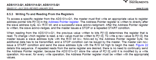
    8.6.2 Conversion Register (P[1:0] = 0h) [reset = 0000h]
    The 16-bit Conversion register contains the result of the last conversion in binary two's complement format.
    Following power-up, the Conversion register is cleared to 0, and remains 0 until the first conversion is completed

    • why is the last conversion stored in 2's complement format..?
    • Do we need to convert this 2's complement to normal binary
    • What do we need to do in case of negative value, should we do sign extension
    • please share some code snippets for the same please

    BR's

    Pawamana Tanjore.

  • Pawamana ,

    these questions will be best answered by Experts in ADC Forum. These are ADC Centric Questions.

    I am going to transfer the question to the appropriate business unit. Thanks for your patience.

    Regards

    Anshu

  • Hi Anshu,

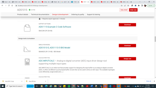
    I saw some documentation relevant to i2c programming recently from TI website.

    Please find the screenshot of  the same, i downloaded the code.

    This code mentioned in below link and screenshot  looks similar to one i tried implementing for ADS1015 ADC (NoRTOS + Free RTOS)

    ADS1115 Example C Code Software

    • can you have  a look of this and reply whether this is meant for sample code for FREERTOS+ NO RTOS(M4F) core..?
    • If so why this link wasn't provided all these days..!
    • If there are more links code snippets similar to this for ADC (ADS1015) interfacing  for different sensors, please share it.
     
  • Pawamana ,

    I am glad you could find resources on ADS115 Product page. i am routing your query to the ADS Experts.

    regards

    Anshu

  • Hi Pawamana,

    I'm sorry for your frustrations.  It would appear that you have found the tools TI has available to communicate to the ADS101x devices.  The latest 'C' code you found is meant to be generic for use with most any microcontroller and requires that when using the software you would need to follow the appropriate driver calls to the I2C peripheral.  You might also want to take a look at the most recent ADS101x-Q1 datasheet as it may be helpful.  This was just recently updated.  Figure 7-10 shows the writing procedure as a timing diagram.  So instead of two back to back writes you can simplify this with a single write to the device to both set the pointer as well as write the configuration.

    I will attempt to answer your specific questions as they relate to the ADS1015, but I may not be able to answer specific questions regarding the usage with the AM64x.  The ADS1015 powers into a low-power state and defaults to single-shot mode of operation.  This means that the device will require bit 15 set to 1 by writing to the configuration register each time you desire to take a conversion.

    So to start a conversion on AIN3/GND you are correct in that the configuration should be set to 0xF583.  So the code snippet you showed appears to be correct.

    8.6.2 Conversion Register (P[1:0] = 0h) [reset = 0000h]
    The 16-bit Conversion register contains the result of the last conversion in binary two's complement format.
    Following power-up, the Conversion register is cleared to 0, and remains 0 until the first conversion is completed

    • why is the last conversion stored in 2's complement format..?
    • Do we need to convert this 2's complement to normal binary
    • What do we need to do in case of negative value, should we do sign extension
    • please share some code snippets for the same please

    The ADC conversion result from the ADS1015 is always going to be binary 2's complement regardless of whether you are using a differential or single-ended input measurement (referenced to GND).  That is to say that the result is always going to be AINP relative to AINN.  As AINN is tied to GND you will be limited to just the +FSR (Full-Scale Range) of the device less any negative going offset.  The advantage of using binary 2's complement is the sign bit will always signal whether the result is positive or negative.  There are many ways of accomplishing the proper sign-extension.  The variable should be either a signed integer or short integer.  What I normally do for this device family is to collect the conversion result that is in the RX buffer and place into a short integer.

    // Assign short signed integer to variable result
    short int result;
    result = (rxBuffer[0])<< 8) | rxBuffer[1];
    //Right-shift binary 2's complement result to 12 bits
    result = result >> 4;

    Let me know if you have other questions related to the ADS1015 specifically.

    Best regards,

    Bob B