This thread has been locked.

If you have a related question, please click the "Ask a related question" button in the top right corner. The newly created question will be automatically linked to this question.

AM6548: How to choose IEP timer for PRU?

Part Number: AM6548

Hi Ti,

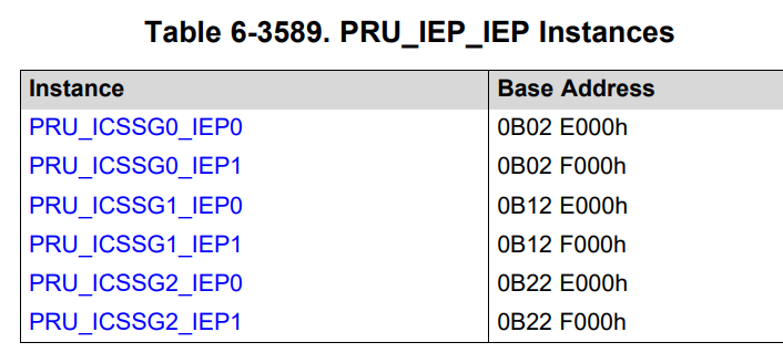
We are using several PRUs in AM65. And from TRM, there are IEP0 and IEP1 inside.

And if there any standard to choose IEP0 or IEP 1 for specific PRUs?

Thanks.

Eric

  • And if there any standard to choose IEP0 or IEP 1 for specific PRUs?

    IEP0 and IEP1 are shared timer instances within ICSSG.  The decision of which IEP to use with PRU is entirely up to PRU firmware architecture.

    Regards

    Pratheesh

  • ,

    That's say, I can use IEP0 or IEP1 for PRU0_0, RTU0_0, TX_PRU0_0, PRU0_1, RTU0_1, TX_PRU0_1?

    If I choose IEP0 but it cannot work, how can I to know what's wrong?

    Eric

  • ,

    I met a problem that one of my PRU can only work with IEP1. But if I change to IEP0, it cannot work.

    My IEP setting is below:

    #define IEPCounter  CT_IEP0

    /* Set PRU Sync-to-VCLK Mode, Clock speed 250MHz*/
    CT_CFG.core_sync_reg_bit.core_vbusp_sync_en = 1;

    /* Set IEP as sync mode, the clock is 250MHz*/
    CT_CFG.iepclk_reg_bit.iep_ocp_clk_en = 1;


    /* Disable counter */
    IEPCounter.global_cfg_reg_bit.cnt_enable = 0;

    /* Reset Count register */
    IEPCounter.count_reg0 = 0xFFFFFFFF;
    IEPCounter.count_reg1 = 0xFFFFFFFF;

    /* Clear overflow status register */
    IEPCounter.global_status_reg_bit.cnt_ovf = 0x1;

    /* Clear compare status */
    IEPCounter.cmp_status_reg = 0xFFFFFFFF;

    /* Set compare values*/
    IEPCounter.cmp0_reg0 = OutFreqMax_ns;
    IEPCounter.cmp0_reg1 = 0;

    /* Enable CMP0 and reset on event */
    IEPCounter.cmp_cfg_reg_bit.cmp_en = 0x1; // enable CMP0 event
    IEPCounter.cmp_cfg_reg_bit.cmp0_rst_cnt_en = 0x1; // enable the reset of counter

    /* Set increment value */
    IEPCounter.global_cfg_reg_bit.default_inc = 4;

    /* Disable compensation */
    IEPCounter.compen_reg_bit.compen_cnt = 0x0;

    /* Enable counter */
    IEPCounter.global_cfg_reg_bit.cnt_enable = 0x1;

    Could you help  to check if anything wrong? 

    Eric

  • /* Set PRU Sync-to-VCLK Mode, Clock speed 250MHz*/
    CT_CFG.core_sync_reg_bit.core_vbusp_sync_en = 1;

    /* Set IEP as sync mode, the clock is 250MHz*/
    CT_CFG.iepclk_reg_bit.iep_ocp_clk_en = 1;

    Can you make sure to do these only one time, you can do this from R5F as well prior to running PRU firmware.

    But if I change to IEP0, it cannot work

    What does not work ? Did you make sure above configuration has taken effect in IEP0 register

  • Hi ,

    /* Set PRU Sync-to-VCLK Mode, Clock speed 250MHz*/
    CT_CFG.core_sync_reg_bit.core_vbusp_sync_en = 1;

    /* Set IEP as sync mode, the clock is 250MHz*/
    CT_CFG.iepclk_reg_bit.iep_ocp_clk_en = 1;

    I will make sure this has been set only one time. I can make sure it execute once when PRU0_0 starts.

    The word "not work" means as below:

    In our program, we have some code as this

    for(;;)
    {
        if (IEPCounter.cmp_status_reg_bit.cmp_status == 0x1) // CMP0 event is issued
        {
            /* Clear CMP0 status */
            IEPCounter.cmp_status_reg_bit.cmp_status = 0x1;
            break;
        }
    }

    If I change to IEP0, it always in the for loop and cannot jumping out the for loop.

    But if I change to IEP1, it can break out the for loop and keep going.

    I'm not sure if the IEP setting has anything wrong.

    Could you help to check?

    Thanks.

    Eric

  • Can you paste IEP0 and IEP1 memory browser screenshots got the ICSSG instance used in non-working and working scenarios?

  • Hi ,

    Not sure if this is what you want. Please let me know if I was wrong.

    IEP1 (working)

    IEP0 (non-working)

    Eric

  • Yes, but this looks like they are all zeros and it should not be, you can either do this from R5F or use 0x2E000 (IEP0) and 0x2F000(IEP1) address respectively for ICSS local memory map.

  • Hi ,

    I got it finally. 

    IEP1 (working)

    IEP0 (not working)

    Eric

  • Looking at register dump, there is a problem with your IEP0 configuration, are you running this firmware stand alone or together with some Industrial Ethernet protocol ?

    /* Set compare values*/
    IEPCounter.cmp0_reg0 = OutFreqMax_ns;
    IEPCounter.cmp0_reg1 = 0;

    /* Enable CMP0 and reset on event */
    IEPCounter.cmp_cfg_reg_bit.cmp_en = 0x1; // enable CMP0 event
    IEPCounter.cmp_cfg_reg_bit.cmp0_rst_cnt_en = 0x1; // enable the reset of counter

    I do not see above taking effect for IEP0, but shadow_en bit set and IEPCounter.cmp0_reg0 = 0. So effectively your IEP count_reg0 will stay at zero always as seen from the logs! Can you try updating above registers via memory browser and see whether it works?

  • Hi ,

    We run the PRU firmware stand alone. 

    And I found one thing. 

    When I only load PRU0_1 with IEP0 from CCS, the compare value reg can be set. And it can break out my for loop above, and it can work.

    After that, I tired to load PRU0_0, which use IEP0 also, and my PRU0_1 cannot work anymore. 

    At the time, I tried to overwrite the compare value from Memory mapping, I cannot do it as well.

    My PRU0_0 iep settting is as below, not sure if they are lated or not.

    /* Enable shadow mode*/
    IEPCounter.cmp_cfg_reg_bit.shadow_en = 1;

    /* Disable counter */
    IEPCounter.global_cfg_reg_bit.cnt_enable = 0;

    /* Reset Count register */
    IEPCounter.count_reg0 = 0xFFFFFFFF;
    IEPCounter.count_reg1 = 0xFFFFFFFF;

    /* Set increment value */
    IEPCounter.global_cfg_reg_bit.default_inc = 4;

    /* Enable counter */
    IEPCounter.global_cfg_reg_bit.cnt_enable = 0x1;

    Eric

  • /* Enable shadow mode*/
    IEPCounter.cmp_cfg_reg_bit.shadow_en = 1;

    Yes, it is related, what are you trying to accomplish here?

  • Hi ,

    My PRU code is coming from our PRU engineer but the reason is unknown anymore.

    After check with TRM, the shadow mode bit looks to enable 32 bit operation. Default is 64 bit. 

    And there is a sentence not very clear. Could you help to explain it?

    "This enable the shadow copy finctionality of the compare registers"

    Eric

  • Yes, for this use case - you cannot run IEP0/1 in shadow mode from one core and normal mode from another core. Shadow mode is used if you need cyclic behavior and, in this case, when CMP0 HIT, period will be copied by HW from upper 32-bit of CMPx register.

    Code you are running does assume 64-bit mode, so configuring SHADOW_EN is not correct.

  • Hi ,

    I tired to do an experiment for my use case.

    While I was running PRU0_1, I tried to control the R30 as high low.

    __R30 = 0;
    for(;;)
    {
    if (IEPCounter.cmp_status_reg_bit.cmp_status == 0x1) // CMP0 event is issued
    {
    /* Clear CMP0 status */
    IEPCounter.cmp_status_reg_bit.cmp_status = 0x1;
    break;
    }
    }
    __R30 = 1;

    Before control R30, we initialize the IEP1 timer below and got the waveform as below. It looks not bad.

    /* Disable counter */
    IEPCounter.global_cfg_reg_bit.cnt_enable = 0;

    /* Reset Count register */
    IEPCounter.count_reg0 = 0xFFFFFFFF;
    IEPCounter.count_reg1 = 0xFFFFFFFF;

    /* Clear overflow status register */
    IEPCounter.global_status_reg_bit.cnt_ovf = 0x1;

    /* Clear compare status */
    IEPCounter.cmp_status_reg = 0xFFFFFFFF;

    /* Set compare values*/
    IEPCounter.cmp0_reg0 = OutFreqMax_ns;
    IEPCounter.cmp0_reg1 = 0;

    /* Enable CMP0 and reset on event */
    IEPCounter.cmp_cfg_reg_bit.cmp_en = 0x1; // enable CMP0 event
    IEPCounter.cmp_cfg_reg_bit.cmp0_rst_cnt_en = 0x1; // enable the reset of counter

    /* Set increment value */
    IEPCounter.global_cfg_reg_bit.default_inc = 4;

    /* Disable compensation */
    IEPCounter.compen_reg_bit.compen_cnt = 0x0;

    /* Enable counter */
    IEPCounter.global_cfg_reg_bit.cnt_enable = 0x1;

    #pragma MUST_ITERATE(1)
    for (i = 0; i < HSPO_Channel; i++, g_pSharedPoCrtl++)
    {
    g_pSharedPoCrtl->hspPOCr = HspPOTypeAB;
    }

    However, when I load PRU0_0, which is running with IEP0, and it only execute IEP setting here. The reset code are cyclic and I remove it for this test.

    void IEPTimer_init(void)
    {
    #if defined(PRU0_0)
    /* Set PRU Sync-to-VCLK Mode, Clock speed 250MHz*/
    CT_CFG.core_sync_reg_bit.core_vbusp_sync_en = 1;

    /* Set IEP as sync mode, the clock is 250MHz*/
    CT_CFG.iepclk_reg_bit.iep_ocp_clk_en = 1;
    #endif


    /* Enable shadow mode*/
    //IEPCounter.cmp_cfg_reg_bit.shadow_en = 1; //I already mark the shadow_en here.

    /* Disable counter */
    IEPCounter.global_cfg_reg_bit.cnt_enable = 0;

    /* Reset Count register */
    IEPCounter.count_reg0 = 0xFFFFFFFF;
    IEPCounter.count_reg1 = 0xFFFFFFFF;

    /* Set increment value */
    IEPCounter.global_cfg_reg_bit.default_inc = 4;

    /* Enable counter */
    IEPCounter.global_cfg_reg_bit.cnt_enable = 0x1;

    }

    The R30 waveform controlled by PRU0_1 becomes not stable. 

    In my though, I don't think it's normal when running PRU0_0 and PRU0_1 at the same time.

    so, could you help to how to do the IEP setting?

    Thanks.

    Eric

  • void IEPTimer_init(void)
    {
    #if defined(PRU0_0)
    /* Set PRU Sync-to-VCLK Mode, Clock speed 250MHz*/
    CT_CFG.core_sync_reg_bit.core_vbusp_sync_en = 1;

    /* Set IEP as sync mode, the clock is 250MHz*/
    CT_CFG.iepclk_reg_bit.iep_ocp_clk_en = 1;
    #endif

    So what sequence are you running this ? PRU0_1 first and generate the pulse via R30 and then PRU0_0, you cannot do above initializations post running PRU0_1!

  • Hi ,

    My sequence is PRU0_0 first and do cyclic programing, and then PRU0_1,  generate pulse, and etc.

    The step I tried is just for test.

    Per my understanding, each PRU should be independent, and will not impact by others.

    So, do you think my IEP setting for PRU0_0 and PRU0_1 is correct? 

    void IEPTimer_init(void)  //This is for PRU0_0
    {
    #if defined(PRU0_0)
    /* Set PRU Sync-to-VCLK Mode, Clock speed 250MHz*/
    CT_CFG.core_sync_reg_bit.core_vbusp_sync_en = 1;

    /* Set IEP as sync mode, the clock is 250MHz*/
    CT_CFG.iepclk_reg_bit.iep_ocp_clk_en = 1;
    #endif


    /* Enable shadow mode*/
    //IEPCounter.cmp_cfg_reg_bit.shadow_en = 1; //I already mark the shadow_en here.

    /* Disable counter */
    IEPCounter.global_cfg_reg_bit.cnt_enable = 0;

    /* Reset Count register */
    IEPCounter.count_reg0 = 0xFFFFFFFF;
    IEPCounter.count_reg1 = 0xFFFFFFFF;

    /* Set increment value */
    IEPCounter.global_cfg_reg_bit.default_inc = 4;

    /* Enable counter */
    IEPCounter.global_cfg_reg_bit.cnt_enable = 0x1;

    }

    And below is for PRU0_1.

    /* Disable counter */
    IEPCounter.global_cfg_reg_bit.cnt_enable = 0;

    /* Reset Count register */
    IEPCounter.count_reg0 = 0xFFFFFFFF;
    IEPCounter.count_reg1 = 0xFFFFFFFF;

    /* Clear overflow status register */
    IEPCounter.global_status_reg_bit.cnt_ovf = 0x1;

    /* Clear compare status */
    IEPCounter.cmp_status_reg = 0xFFFFFFFF;

    /* Set compare values*/
    IEPCounter.cmp0_reg0 = OutFreqMax_ns;
    IEPCounter.cmp0_reg1 = 0;

    /* Enable CMP0 and reset on event */
    IEPCounter.cmp_cfg_reg_bit.cmp_en = 0x1; // enable CMP0 event
    IEPCounter.cmp_cfg_reg_bit.cmp0_rst_cnt_en = 0x1; // enable the reset of counter

    /* Set increment value */
    IEPCounter.global_cfg_reg_bit.default_inc = 4;

    /* Disable compensation */
    IEPCounter.compen_reg_bit.compen_cnt = 0x0;

    /* Enable counter */
    IEPCounter.global_cfg_reg_bit.cnt_enable = 0x1;

    Thanks.

    Eric