This thread has been locked.

If you have a related question, please click the "Ask a related question" button in the top right corner. The newly created question will be automatically linked to this question.

AM6546: JTAG Connection on Target HW not working

Part Number: AM6546
Other Parts Discussed in Thread: TMDX654IDKEVM

Hello,

on our Target HW the SOC AM6546 is not responding on request from the XDS110 Debug probe.

XDS 110 Debug Probe is connected als follows:

  1 o -------------- TMS

  3 o -------------- TDI

  5 o -------------- 3.3V

  7 o -------------- TDO

11 o -------------- TCK

  2 o -------------- RESET

10 o -------------- GND

Before we switched over to our Target HW we were using the TMDX654IDKEVM Evaluation Board.

I tested the XDS 110 Debug Probe with exactly the same connection as described above plus an additional line on pin 8 called SEL_XDS110_INV.

This line is nedded to switch off the onboard JTAG adapter and to enable the external JTAG

The XDS110 Debug Probe connected to the JTAG connector works fine. I can connect, load SW and debug it.

I checked the JTAG signals with a logic analyzer and I see all JTAG signals

On the Target HW I see the following:

  • RESET goes HI
  • TCK starts
  • Test Logic Reset (more than 40msec)
  • Then Signals on TMS and TDI
  • TDO stays continously HI

The decodes JTAG protocol is added as file Target_HW_JTAG_Protocol.txt. See at the end.

The TDO line is all the time on 3.3V. Then I connected a 4.7kOhm resistor from TDO to GND and I measure a voltage of 0.5V.

TDO is of type output or tri-state. So if it is an output I think I should measure a value above 3V. And if it is in tri-state I should measure a voltage of 0V. So it looks that there is TDO not enabled on the SOC. If I calculate it back it looks like that there is a pull-up resistor of 26kOhm connected to TDO.

The EMU0 and EMU1 pins are connected to 3.3V via 22kOhm resistors. Except the EMU0 and EMU1 we have no HW BOOT-MODE configuration. So what is the Default boot-mode ? Is JTAG availabel in this case?

Thanks in advance and best regards

Ron

Target_HW_JTAG_Protocol.txt

  • Hello,

    our Target HW is brandnew. So it could possibly the problem that the SOC AM6546 is not alive.

    Is there an easy way to check if the SOC is alive ?

    The only thing I could check was that the crystal is working correctly with 25MHz.

    Thanks in advance and best regards

    Ron

  • Ron,

    Our expert is currently out of office, returning next week so please expect a delay in responses.

    In order to expedite, can you provide some additional detail such as the full part number of the AM65 device? What software are you using to attempt to connect to the device, and when is the JTAG connection failing (i.e. trying to connect to a core?).

    Do you see the RESETSTATz signal go low to high on power up?

    Thanks,

    Chris

  • Hi Christopher,

    thanks for your response.

    • The SOC on our Target-HW is labeld as follows:

    AM6546 BACDXA

    21P1T1Q

    900    ACD    G1

    • We are using CCS 12.1.0 for development and Debugging. This works fine with the TI Eval-Board TMDX654IDKEVM and XDS100 Debug Probe, but not on our Target-HW.

    • Connecting to the JTAG is failing after this sequence that I saw on the Analyzer

    - RESET goes HI

    - TCK starts

    - Test Logic Reset (more than 40msec)

    - Then Signals on TMS and TDI

    - TDO stays continously HI

    • On power up Reset is low and goes high wenn trying to connect

    Thanks and best regards

    Ron

  • Hi,

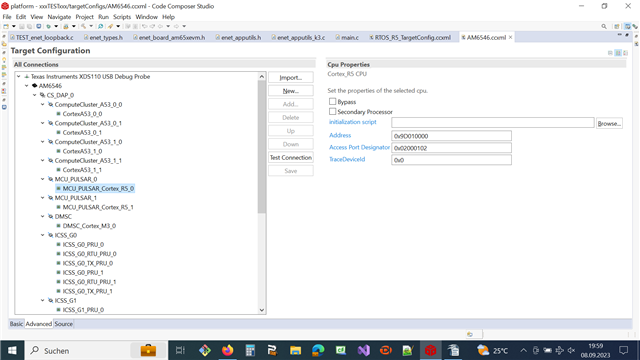
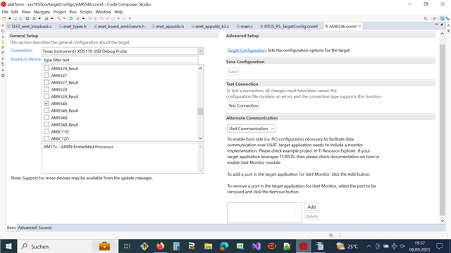
    here is some additional information about Target Configuration. For that I created a new project and tested the XDS110-JTAG on the TI Eval-Board TMDX654IDKEVM and on our Target-HW. Here are the screenshots:

    This target Configuration works fine on the TI Eval-Board TMDX654IDKEVM and the when I click the button TEST CONNECTION the final results is:

    The JTAG DR Integrity scan-test has succeeded.

    This Target Configuration does not work on our Target-HW (see output below)

    [Start: Texas Instruments XDS110 USB Debug Probe]

    Execute the command:

    %ccs_base%/common/uscif/dbgjtag -f %boarddatafile% -rv -o -S integrity

    [Result]

    -----[Print the board config pathname(s)]------------------------------------

    C:\Users\DEV\AppData\Local\TEXASI~1\CCS\

    ccs1210\0\0\BrdDat\testBoard.dat

    -----[Print the reset-command software log-file]-----------------------------

    This utility has selected a 100/110/510 class product.

    This utility will load the adapter 'jioxds110.dll'.

    The library build date was 'Sep 20 2022'.

    The library build time was '12:28:44'.

    The library package version is '9.9.0.00040'.

    The library component version is '35.35.0.0'.

    The controller does not use a programmable FPGA.

    The controller has a version number of '5' (0x00000005).

    The controller has an insertion length of '0' (0x00000000).

    This utility will attempt to reset the controller.

    This utility has successfully reset the controller.

    -----[Print the reset-command hardware log-file]-----------------------------

    The scan-path will be reset by toggling the JTAG TRST signal.

    The controller is the XDS110 with USB interface.

    The link from controller to target is direct (without cable).

    The software is configured for XDS110 features.

    The controller cannot monitor the value on the EMU[0] pin.

    The controller cannot monitor the value on the EMU[1] pin.

    The controller cannot control the timing on output pins.

    The controller cannot control the timing on input pins.

    The scan-path link-delay has been set to exactly '0' (0x0000).

    -----[An error has occurred and this utility has aborted]--------------------

    This error is generated by TI's USCIF driver or utilities.

    The value is '-233' (0xffffff17).

    The title is 'SC_ERR_PATH_BROKEN'.

    The explanation is:

    The JTAG IR and DR scan-paths cannot circulate bits, they may be broken.

    An attempt to scan the JTAG scan-path has failed.

    The target's JTAG scan-path appears to be broken

    with a stuck-at-ones or stuck-at-zero fault.

    [End: Texas Instruments XDS110 USB Debug Probe]

    Thanks and best regards

    Ron

  • What do you mean when saying "we have no HW BOOT-MODE configuration"?  What logic state is your design applying to the bootmode inputs before the rising edge of reset?

    I hope your design doesn't allow any enabled inputs to float since the shoot-through current associated with this condition could damage the input buffers if the condition is allowed to persist for long periods of time.

    I'm not an expert on the data transfer over JTAG port but seem to recall reading something in the IEEE 1149 specification that says the output buffer associated with TDO remains disabled until data is actively being scanned out of the device. It appears the AM6545 device is not functional based on your observation of TDO never driving a valid logic level when trying to connect the debugger.

    You should apply a valid boot mode to the bootmode inputs if this is not being done, then verify all power supplies and resets have been applied with the appropriate power-up sequence. It may help to contrast your power supply and reset sequencing to the TMDX654IDKEVM Evaluation Board.

    Regards,
    Paul

  • Hi Paul,

    thanks for your answer.

    Is there an example where we can see how to connect the BOOT-MODE pins in order to get JTAG enabled right after reset ?

    Thanks in advance and

    best regards

    Ron
  • The TRM should have a section that discusses the various boot mode options and the logic levels that must be present on the inputs to select each mode.

    The TI EVM is a good example of what should be done with these inputs.

    Regards,
    Paul