This thread has been locked.

If you have a related question, please click the "Ask a related question" button in the top right corner. The newly created question will be automatically linked to this question.

AM623: Cannot establish Ethernet RMII data communication(Tx/Rx) between MAC and PHY

Part Number: AM623
Other Parts Discussed in Thread: SK-AM62, , DP83825I, AM625

Greetings,

We have designed Ethernet RMII communication circuit on our new PCB using TI MCU and PHY.
When Ethernet cable connects from this PCB to PC for the test, link up can be done (100Mbps, Full-duplex) but ping cannot success.

Parts name of MCU and PHY are the followings.
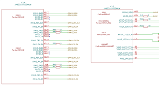
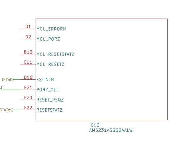
  MCU: AM6231ASGGGAALW
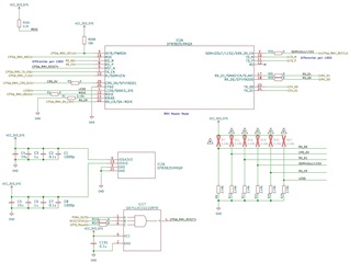
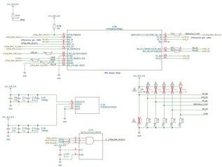
  PHY: DP83825IRMQR  x2 (eth0, eth1) used as RMII master mode

We have designed the firmware of Ethernet communication module based on the one for SK-AM62.
(Changed only some parameters and defines from for RGMII mode to for RMII mode.)

We have confirmed that the port mode setect of both eth0/eth1 is RMII.
  CTRL_ENET1_CTRL Register (Offset = 4044h) ENET1_CTRL_PORT_MODE_SEL: b001 - RMII
  CTRL_ENET2_CTRL Register (Offset = 4048h) ENET2_CTRL_PORT_MODE_SEL: b001 - RMII
  CTRL_ENET1_CTRL_PROXY Register (Offset = 6044h) ENET1_CTRL_PORT_MODE_SEL_PROXY: b001 - RMII
  CTRL_ENET2_CTRL_PROXY Register (Offset = 6048h) ENET2_CTRL_PORT_MODE_SEL_PROXY: b001 - RMII

Details of ping NG;
  PC --> PCB: PC send ARP request to PCB(as global packet), but PCB send no response message to PC.
  PCB --> PC: PCB send ARP request to PC(as global packet), then PC send the response message to PCB, but then PCB send ARP request to PC(as global packet) again. It repeats until ping command of PCB is stopped.

We measured the waveform of main signal lines around PHY.
The waveforms of MDIO, MDC, 50MHzOut, TD_P/M, RD_P/M has the correct changes and seem no problem.
But the waveforms of TX_EN, TX_D0, TX_D1, RX_D0, RX_D1, RX_ER, CRS_DV are always 0V with no change.

Please give us some advice if it can be guessed something suspicious by the above information, or if there are what we need to check more.


Thanks,
Nakashima

  • Hello nakashima.bo

    Thank you for the query.

    I need more information on the interface. 

    Is this something you could share.

    Looks like the MII side of the EPHY is not functional. Are all the power supplies as expected including supply ramp.

    Regards,

    Sreenivasa

  • Hello Mr. Sreenivasa,

    Thanks for your reply.

    >>Are all the power supplies as expected including supply ramp.
    Yes, as far as we have confirmed.

    I attach the schematic diagram of Ethernet circuit between AM6231 and DP83825IRMQR as followings.
    Please confirm the details.

    <Around AM623>


    <Around PHY (RMII0(eth0) side)>


    <Around PHY (RMII1(eth1) side)>


    Thanks,
    Nakashima

  • Hello Nakashima,

    Thank you for the note.

    I will need PDF which is searchable to be able to review.

    I see the EPHY configured as master.

    I need information on the clock input to the EPHY.

    Regards,

    Sreenivasa

  • HI Mr. Sreenivasa,

    Thanks for your quick reply.

    >>I will need PDF which is searchable to be able to review.
    >>I need information on the clock input to the EPHY.
    I have made the attached PDF file which is picked up Ethernet circuit between MCU and PHY and around PHY from the circuits of our PCB, as your request.
    The clock circuit includes in it so you can find the info of clock input.
    Please confirm the PDF file.

    >>I see the EPHY configured as master.
    Yes, we have designed the PHY configure as master.

    I understand that master/slave is not determined by auto negotiation between two devices on RMII mode, so both two devices needs configure master/slave by themselves before the link-up.

    I have questions, PHY DP83825IRMQR can configure as master, but does MCU AM623 also need to configure as slave by any software settings?
    And, is there any method which we can confirm master/slave setting of each Ethernet port(eth0, eth1, ...) on MCU AM623?

    Thanks,
    Nakashima

    EthernetCircuit20230914.pdf

  • Hello Nakashima,

    Thank you for the inputs.

    Let me review the inputs and update you.

    Regards,

    Sreenivasa

  • Hello Nakashima,

    As i review the schematics, could you please have the EPHY schematics reviewed from the Ethernet PL.

    Please start a new thread with title DP82835i Ethernet interface check. Do not include the SoC name.

    Regards,

    Sreenivasa

  • Hello Nakashima,

    Could you conform the implementation in the design is as below - MCU_PORz is not connected.

    Regards,

    Sreenivasa

  • Hello Nakashima,

    I am assuming some of the nets were deleted while providing the schematics and not able to trace the implementation.

    EX: 25M SoC clock is not visible. LFOSC0 is not connected. When not used Xi needs to be terminated. WKUP_I2c0 is not terminated. This needs to be terminated irrespective of the use case.

    Verify the below section of the DP83825i data sheet 

    6.6 Timing Requirements

    Follow the AM625 for the reset implementation.

    Use either RESETSTSTz or PORz_OUT. the IO needs to be pulled up to strap the Ethernet configuration during poweer-up.

    Please review the schematics with respect to SK for any additional errors and verify the EPHY clock input and reset requirements as per data sheet are followed.

    Regards,

    Sreenivasa

  • Hello Sreenuvasa-san,

    Thanks for your reply.

    As Machida-san informed you on the following thread soon before, we are the customer of his company and the Ethernet comm issue on this thread is all what we have. 
    https://e2e.ti.com/support/processors-group/processors/f/processors-forum/1257955/am623-how-user-can-assert-tx_en/4816081#4816081

    The schematic information about clock and reset, which you have required on the last reply, are included in the schematic diagram files which Machida-san had shared to you before on private message.
    So, would you please share these files to your colleague Schuyler-san, and confirm them?

    If these files are not enough for you to investigate about this issue, you need more information or you want us to test on the PCB, please ask me.


    Thanks,
    Nakashima

  • Hello Nakashima

    Thank you.

    Below is the issue reported:

    We measured the waveform of main signal lines around PHY.
    The waveforms of MDIO, MDC, 50MHzOut, TD_P/M, RD_P/M has the correct changes and seem no problem.
    But the waveforms of TX_EN, TX_D0, TX_D1, RX_D0, RX_D1, RX_ER, CRS_DV are always 0V with no change.

    Can you confirm if this is the issue you are seeing?

    If would expect some activity on the EPHY output (RX) when the PHY power up and configured.

    Regards,

    Sreenivasa

  • Hello Sreenivasa-san,

    Thanks for your reply.
    I confirmed the EPHY output (RX; RX_D0, RX_D0, RX_ER, CRS_DV) when the EPHY power up and configured, as your request.

    The results are followings.
    1) RX_D0 on RMII1(eth1) side raised up from 0V to 3.3V for a moment, but then down to 0V and had never raised up again after it.
    2) Other RX outputs on RMII1(eth1) side except for RX_D0 and all RX outputs on RMII0(eth0) side were always 0V before/after EPHY power up.

    The latest pull-up/pull-down implementation for straps configuration are the followings, which I shared to you on this thread before.
    The behavior of 1) is because only this output line is pull-up, and it can guess that PHY set RX_D0 output to low soon after reading straps configuration was completed.


    Best regards,
    Nakashima

  • Hello Nakashima

    Thank you.

    Let me review the inputs and the schematics and come back.

    Regards,

    Sreenivasa

  • Morning Sreenivasa-san,

    Have there been any progress on your confirmation after your last reply?
    If possible, please tell me your current situation, and your forecast when you can reply comments to us.


    Thanks,
    Nakashima

  • Hi,

    I am going on the first post in the thread. Since there is a clock, how is link up being detected?

    Please attach the output of the following commands, these are based for the first Ethernet port, eth0:

    before the ping command:

    ifconfig - a

    ethtool eth0

    ethtool -S eth0

    Then do a ping command and please repeat the same commands. 

    Best Regards,

    Schuyler

  • Hello Schuyler-san,

    Thanks for your reply.

    I took the output logs from AM6231 when did running the commands "ifconfig -a", "ethtool ethN" and "ethtool -S ethN" based on your request, for both eth0 and eth1.
    On the laptop PC, IPv4 setting was followings and the firewall setting was invalid.
      IPv4 address: 192.168.2.5
      Subnet mask: 255.255.255.0

    I ran these commands on the following three situations.
      1) Before link up (= Before connect LAN cable between PCB and the laptop PC)

      2) After link up, but before doing ping command
      3) After doing ping command

    Please confirm the attached logs.

    Thanks,
    Nakashima

    0486.eth0.txt
    Fullscreen
    1
    2
    3
    4
    5
    6
    7
    8
    9
    10
    11
    12
    13
    14
    15
    16
    17
    18
    19
    ifconfig -a
    eth0 Link encap:Ethernet HWaddr 34:08:E1:87:A8:CA
    UP BROADCAST MULTICAST MTU:1500 Metric:1
    RX packets:0 errors:0 dropped:0 overruns:0 frame:0
    TX packets:0 errors:0 dropped:0 overruns:0 carrier:0
    collisions:0 txqueuelen:1000
    RX bytes:0 (0.0 B) TX bytes:0 (0.0 B)
    eth1 Link encap:Ethernet HWaddr 86:FC:63:9F:ED:1A
    UP BROADCAST MULTICAST MTU:1500 Metric:1
    RX packets:0 errors:0 dropped:0 overruns:0 frame:0
    TX packets:0 errors:0 dropped:0 overruns:0 carrier:0
    collisions:0 txqueuelen:1000
    RX bytes:0 (0.0 B) TX bytes:0 (0.0 B)
    lo Link encap:Local Loopback
    inet addr:127.0.0.1 Mask:255.0.0.0
    inet6 addr: ::1/128 Scope:Host
    UP LOOPBACK RUNNING MTU:65536 Metric:1
    XXXXXXXXXXXXXXXXXXXXXXXXXXXXXXXXXXXXXXXXXXXXXXXXXX

    8738.eth1.txt
    Fullscreen
    1
    2
    3
    4
    5
    6
    7
    8
    9
    10
    11
    12
    13
    14
    15
    16
    17
    18
    19
    root@am62xx-evm:~# ifconfig -a
    eth0 Link encap:Ethernet HWaddr 34:08:E1:87:A8:CA
    inet6 addr: fe80::3608:e1ff:fe87:a8ca/64 Scope:Link
    UP BROADCAST MULTICAST MTU:1500 Metric:1
    RX packets:0 errors:0 dropped:0 overruns:0 frame:0
    TX packets:63 errors:0 dropped:0 overruns:0 carrier:0
    collisions:0 txqueuelen:1000
    RX bytes:0 (0.0 B) TX bytes:8696 (8.4 KiB)
    eth1 Link encap:Ethernet HWaddr 86:FC:63:9F:ED:1A
    UP BROADCAST MULTICAST MTU:1500 Metric:1
    RX packets:0 errors:0 dropped:0 overruns:0 frame:0
    TX packets:0 errors:0 dropped:0 overruns:0 carrier:0
    collisions:0 txqueuelen:1000
    RX bytes:0 (0.0 B) TX bytes:0 (0.0 B)
    lo Link encap:Local Loopback
    inet addr:127.0.0.1 Mask:255.0.0.0
    inet6 addr: ::1/128 Scope:Host
    XXXXXXXXXXXXXXXXXXXXXXXXXXXXXXXXXXXXXXXXXXXXXXXXXX


  • Hello Nakashima

    I was reviewing the schematics and had few suggestions for you to check.

    Verify the below section of the DP83825i data sheet
    6.6 Timing Requirements

    Check supply ramp 

    Add pullup near to pin 6 of the AND gate
    GPIO_Reset

    Add pulldown on the EPJY reset input pin
    CPSW_RMII_RESETn

    Can you pls make the hardware changes and do a test.

    Regards,

    Sreenivasa

  • Hello Nakashima

    Any thoughts if you have the EPHY implementation reviewed by the EPHY team?

    Regards,

    Sreenivasa

  • Hello Sreenivasa-san,

    I tried to do the test after the hardware change which you suggest, but the behavior was not changed and not improved from before.

    >>Any thoughts if you have the EPHY implementation reviewed by the EPHY team?
    I am very sorry, but I cannot understand what you want to ask me by this comment...
    I believe that EPHY implementation on our PCB which is written on our schematic diagram has been already reviewed by EPHY team via Schuyler-san, and if we would take any feedback comments and suggestions from the EPHY team, we will try it.

    Best regards,
    Nakashima

  • Hello Nakashima,

    Thank you.

    >>Any thoughts if you have the EPHY implementation reviewed by the EPHY team?
    I am very sorry, but I cannot understand what you want to ask me by this comment...
    I believe that EPHY implementation on our PCB which is written on our schematic diagram has been already reviewed by EPHY team via Schuyler-san, and if we would take any feedback comments and suggestions from the EPHY team, we will try it.

    We have an Ethernet team who could review the EPHY implementation 

    Please start a new thread with title:  DP82835 EPHY schematics review and attach the EPHY schematics page for the EPHY team to review as we continue to discuss in this thread.

    Regards,

    Sreenivasa 

  • Hello Sreenivasa-san,

    Thanks for your advice.

    I started new thread as followings.
    https://e2e.ti.com/support/interface-group/interface/f/interface-forum/1275932/dp83825i-ephy-schematics-review

    The discussion about this issue will proceed on this new EPHY thread from now on, so shall I close this AM62x MCU thread?

    Regards,
    Nakashima

  • Hi,

    I will close this close this thread for the time being as a new thread has been started for this issue.

    Best Regards,

    Schuyler

  • Dear SoC experts,

    We have discussed about this issue with PHY expert on the following thread.
    https://e2e.ti.com/support/interface-group/interface/f/interface-forum/1275932/dp83825i-ephy-schematics-review

    His opinion is that the diagram around PHY is no problem and the PHY is operating normally from the confirmation results so far, and he ask me to follow-up with the SoC team to further discuss possible causes on the SoC side.
    It can be shown on around the end of this thread.

    Would you please confirm whole of this thread, and consider about the causes of this issue in your team again?

    Thanks,
    Nakashima