This thread has been locked.

If you have a related question, please click the "Ask a related question" button in the top right corner. The newly created question will be automatically linked to this question.

TDA4VM: Configure User_LED1 and User_LED2 to be toggled as HEARTBEAT

Part Number: TDA4VM

Hello.

I would ask TI experts how should I define DTS for j721e board in order to have LD8 and LD9 (connected to IOEXPANDER2 outputs 23 and 24) togling with linux trigger heartbeat.

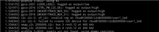
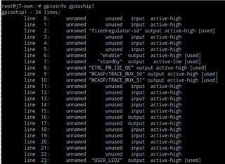
Doing tests, I am able to make LD8 active defining it as GPIO-hog, but I can not  see LD9 togling. 

This is the piece of DTS (I have not used overlay, I have just chaged "k3-j721e-common-proc-board.dts")

&main_i2c0 {
	pinctrl-names = "default";
	pinctrl-0 = <&main_i2c0_pins_default>;
	clock-frequency = <400000>;

	exp1: gpio@20 {
		compatible = "ti,tca6416";
		reg = <0x20>;
		gpio-controller;
		#gpio-cells = <2>;
	};

	exp2: gpio@22 {
		compatible = "ti,tca6424";
		reg = <0x22>;
		gpio-controller;
		#gpio-cells = <2>;
		
		P23-hog {
			/* USER_LED2*/
			gpio-hog;
			gpios = <23 GPIO_ACTIVE_HIGH>;
			output-low;
			line-name = "USER_LED2";
		};

		p08-hog {
			/* P10 - PM_I2C_CTRL_OE */
			gpio-hog;
			gpios = <8 GPIO_ACTIVE_HIGH>;
			output-high;
			line-name = "CTRL_PM_I2C_OE";
		};

		p09-hog {
			/* P11 - MCASP/TRACE_MUX_S0 */
			gpio-hog;
			gpios = <9 GPIO_ACTIVE_HIGH>;
			output-high; /*Ficosa: Activate TRACE lines*/
			line-name = "MCASP/TRACE_MUX_S0";
		};

		p10-hog {
			/* P12 - MCASP/TRACE_MUX_S1 */
			gpio-hog;
			gpios = <10 GPIO_ACTIVE_HIGH>;
			output-high;
			line-name = "MCASP/TRACE_MUX_S1";
		};
	};

	user1_led{
	    compatible = "gpio-leds";
	    label = "user1_led";
	    gpios = <&exp2 22 GPIO_ACTIVE_HIGH>; 
	    default-state = "on";
	    linux,default-trigger = "heartbeat";
    };
};

I have confirmed CONFIG_LEDS_TRIGGER_HEARTBEAT= y in kernel config.

Any tip?

Thanks

  • Hi Pablo,

    I would recommend referencing k3-j721s2-common-proc-board.dts which is the dts file for the common processor board when using the J721S2 SOM board. The common processor board is common for both J721E and J721S2, so the IO expander should be on the same I2C address, and J721S2 dts file defines all the GPIO connected to the expander: https://git.ti.com/cgit/ti-linux-kernel/ti-linux-kernel/tree/arch/arm64/boot/dts/ti/k3-j721s2-common-proc-board.dts?h=ti-linux-6.1.y#n419

    These GPIO pins should come up within Linux if using the gpioinfo command.

    Regards,

    Takuma

  • I have checked content and I realize there is no diference about that pin. 

    I would like to know if is it possible to define that IOEXPANDER ouput as a GPIO - led compatible with heartbeat.

     I have tested diferent ways, compilation is not warning but I receive this message on kernel boot:

  • Hi Pablo,

    We have not tried the Linux kernel heartbeat with the expander, but our driver is compatible with standard tools such as chardev GPIO, so I do not see any reasons why this would not work.

    To troubleshoot, are you able to toggle this pin manually using gpioset without using the heartbeat kernel? Would like to make sure the correct pins are being set up in device tree, compiled correctly, flashed correctly, and is being toggled.

    Regards,

    Takuma

  • Yes, I can.

    1.- When I do not define P22 as hog, I see this in gpioset

    2.- Then, I can activate - deactivate line 22 using gpioset gpiochip1 22=0 & gpioset gpiochip1 22=1. Led is correctly activate or deactivated. Then I can togle it manually

    The problem is when I try to define that pin as a led in DTS. I do not receive any error/warning in DTB compilation, and I don't see user1_led in gpioinfo

    As I am newbee, I am pretty sure I forget something or I make any mistake. This is a piece of code in k3-j721e-common-board.dts

    	user1_led{
    	    compatible = "gpio-leds";
    	    label = "user1_led";
    	    gpios = <&exp2 22 GPIO_ACTIVE_HIGH>; 
    	    default-state = "on";
    	    linux,default-trigger = "heartbeat";
    	    status = "okay";
        };

    Could you please let me know how I can define led into that ioexpander in DTS? Or maybe is incompatible?  

    BR

  • Finally I solved issue just moving node outside of &main_i2c0 and definining leds node:

    / {
    	chosen {
    		stdout-path = "serial2:115200n8";
    		bootargs = "console=ttyS2,115200n8 earlycon=ns16550a,mmio32,0x02800000 root=/dev/mmcblk1p2 rw rootfstype=ext4 rootwait";
    	};
    
    	dma_buf_phys {
    		compatible = "ti,dma_buf_phys";
    	};
    
    	gpio_keys: gpio-keys {
    		compatible = "pvarela-gpio";
    		//compatible = "gpio-keys";
    		autorepeat;
    		pinctrl-names = "default";
    		/*PVARELA*/
    		pinctrl-0 = <&sw10_button_pins_default &sw11_button_pins_default>;
    		//pinctrl-0 = <&sw11_button_pins_default>;
    
    		/*PVARELA*/
    		sw10: sw10 {
    			label = "GPIO Key USER1 PVARELA3";
    			linux,code = <BTN_0>;
    			gpios = <&main_gpio0 0 GPIO_ACTIVE_LOW>;
    		};
    
    		sw11: sw11 {
    			label = "GPIO Key USER2 PVARELA3";
    			linux,code = <BTN_1>;
    			gpios = <&wkup_gpio0 7 GPIO_ACTIVE_LOW>;
    		};
    	};
    
    
    	leds {
    	    compatible = "gpio-leds";
    	    
    	    user1_led{
    		    label = "user1_led";
    		    gpios = <&exp2 22 GPIO_ACTIVE_HIGH>; 
    		    default-state = "on";
    		    linux,default-trigger = "heartbeat";
    		    status = "okay";
    		};
    
    		user2_led{
    		    label = "user2_led";
    		    gpios = <&exp2 23 GPIO_ACTIVE_HIGH>; 
    		    default-state = "on";
    		    linux,default-trigger = "heartbeat";
    		    status = "okay";
    		};
        };

    Now I see Heartbeating on LEDS connected to Io Expander.

    Thanks