TDA4VH-Q1: MCU2_0 register WKUP_GPIO interrupts,but it caused some problems

Part Number: TDA4VH-Q1

Hi,

SDK:8.6

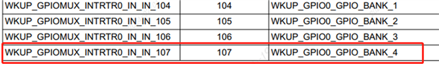
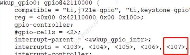
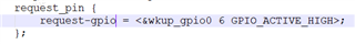
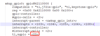
I need to use WKUP_GPIO8 and WKUP_GPIO70 in MCU2_0 to capture the rising interrupts.

When I choose WKUP_GPIO8, belonging to banknum=0, interrupt can register successfully, but choose WKUP_GPIO70, belonging to banknum=4, failed to interrupt registration.

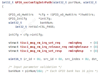
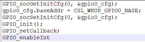
Here is the api for the gpio interrupt registration I used on mcu2_0.

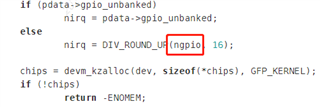
When I checked the PDK, I found some logical errors, as shown in the following figure. When banknum>2, it will never enter interrupt registration.

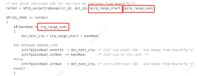
This means that when banknum>2, no GPIO can apply for interruption.

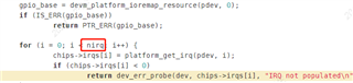
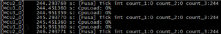
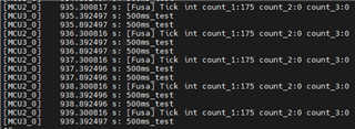
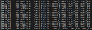
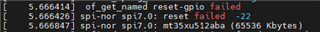
When I modified the judgment logic, I indeed applied for an interrupt, and  MCU2_0 did indeed capture data from WKUP_GPIO70,but it caused the GPIO driver application on A72 to fail. When checking the error location, it was found that the registration of GPIO irq in the driver failed. May I ask what is the connection between these two?Does A72 cause this problem because MCU2_0 registered WKUP_GPIO interrupt?

  • Hi mingsheng,

    I will speak to the team and get back to you about this issue tomorrow.

    Thanks,
    Neehar

  • Hi mingsheng,

    This irq_range_num limit is set to allocate resources among all the cores and allow for equal resources for each core. This is set in the boardcfg and can be manipulated if you wish. 

    Is there a reason you want to use bankNum=4 for WKUP_GPIO? 

    Thanks,

    Neehar

  • In terms of hardware design, my board needs to use the pin WKUP_GPIO70 as an interrupt to capture the rising edge.

    WKUP_GPIO70 in pdk is banknum =4,When I call GPIO_init(), as shown in the figure below.

    And even though I'm using WKUP_GPIO8, banknum=0, A72 will print with gpio irq registration failure.

    So,I think there are two questions here,

    1、Can I use WKUP_GPIO's interrupt on MCU2_0?

    2、Why does an interruption of MCU2_0 using WKUP_GPIO cause A72 interrupt registration failure?

  • Hi mingsheng,

    Can I use WKUP_GPIO's interrupt on MCU2_0?

    Yes, you can.

    Why does an interruption of MCU2_0 using WKUP_GPIO cause A72 interrupt registration failure?

    Can you try using a separate base address for MCU2_0? You can do this by using a different macro from the cslr_soc_baseaddress.h. There may be some interrupt conflicts between A72 and MCU2_0 as you are using the same base addresses.

    Thanks,

    Neehar

  • Hi Neehar,

    I don't understand how to use a separate base address for MCU2_0, is there any demo to show it?

  • Hi mingsheng,

    You can modify either the base address for MCU2_0 by adjusting the gpio0_cfg and setting to a different macro from the cslr_soc_baseaddress.h (for ex. CSL_GPIO0_BASE). Or you can modify the wkup_gpio address in the dts, for example, "wkup_gpio0: gpio@600000".

    Thanks,
    Neehar

  • Hi Neehar,

    I did what you said, but it didn't work.

    1、I changed the dts, just like you said

    wkup_gpio0: gpio@600000 {

    compatible = "ti,j721e-gpio", "ti,keystone-gpio";

    reg = <0x00 0x42110000 0x00 0x100>;

    gpio-controller;

    #gpio-cells = <2>;

    interrupt-parent = <&wkup_gpio_intr>;

    interrupts = <103>, <104>, <105>, <106>, <107>, <108>;

    interrupt-controller;

    #interrupt-cells = <2>;

    ti,ngpio = <89>;

    ti,davinci-gpio-unbanked = <0>;

    power-domains = <&k3_pds 167 TI_SCI_PD_EXCLUSIVE>;

    clocks = <&k3_clks 167 0>;

    clock-names = "gpio";

    status = "disabled";

    };

    It did not report interrupt error again in A72, but also did not receive interrupt signal in MCU2_0.

    This means that it does not solve my problem of capturing wkup_gpio's rising interrupts  in MCU2_0,and does not cause A72 interrupt registration failure.

    2、I used CSL_GPIO0_BASE for gpio0_cfg, but also did not receive interrupt signal in MCU2_0.

    ret = GPIO_socGetInitCfg(0, &gpio0_cfg);
    if(0 != ret) {
    goto exit_init;
    }
    gpio0_cfg.baseAddr = CSL_GPIO0_BASE;
    gpio0_intCfg = gpio0_cfg.intCfg;
    gpio0_intCfg[70].eventId= 0;
    gpio0_intCfg[70].intcMuxNum=INVALID_INTC_MUX_NUM;
    gpio0_intCfg[70].intcMuxInEvent=0;
    gpio0_intCfg[70].intcMuxOutEvent=0;
    ret = GPIO_socSetInitCfg(0, &gpio0_cfg);
    if(0 != ret) {
    goto exit_init;
    }

    And the PDK code :

    int32_t GPIO_socConfigIntrPath(uint32_t portNum, uint32_t pinNum,void *hwAttrs,bool setIntrPath)
    {

    GPIO_v0_HwAttrs *cfg = (GPIO_v0_HwAttrs *)hwAttrs;
    GPIO_IntCfg *intCfg;
    uint32_t bankNum;
    int32_t retVal=CSL_PASS;

    intCfg = cfg->intCfg;

    struct tisci_msg_rm_irq_set_req rmIrqReq = {0};
    struct tisci_msg_rm_irq_release_req rmIrqRelease = {0};
    struct tisci_msg_rm_irq_set_resp rmIrqResp = {0};

    uint16_t ir_id = 0U, src_id = 0U, src_index = 0U, dst_id, dst_host_irq, irq_range_start, irq_range_num;

    /* Input parameter validation */
    bankNum = pinNum/16U; /* Each GPIO bank has 16 pins */

    /* GPIO uses bank interrupts. So choose the bank interrupts from bus_gpio_bank with valid values from
    * the DMSC firmware user guide */
    /* We route bank interrupts to the cpu interrupts */
    switch (cfg->baseAddr)
    {
    case (uint32_t)CSL_WKUP_GPIO0_BASE:
    ir_id = TISCI_DEV_WKUP_GPIOMUX_INTRTR0;
    src_id = TISCI_DEV_WKUP_GPIO0;
    src_index = (uint16_t)bankNum; /* This is the bus_gpio_bank (0-5) mentioned in DMSC firmware guide for J784S4_DEV_WKUP_GPIO0 */
    break;
    case (uint32_t)CSL_WKUP_GPIO1_BASE:
    ir_id = TISCI_DEV_WKUP_GPIOMUX_INTRTR0;
    src_id = TISCI_DEV_WKUP_GPIO1;
    src_index = (uint16_t)bankNum; /* This is the bus_gpio_bank (0-5) mentioned in DMSC firmware guide for J784S4_DEV_WKUP_GPIO1 */
    break;
    case (uint32_t)CSL_GPIO0_BASE:
    ir_id = TISCI_DEV_GPIOMUX_INTRTR0;
    src_id = TISCI_DEV_GPIO0;
    src_index = (uint16_t)bankNum; /* This is the bus_gpio_bank (0-7) mentioned in DMSC firmware guide for J784S4_DEV_GPIO0 */
    break;
    case (uint32_t)CSL_GPIO2_BASE:
    ir_id = TISCI_DEV_GPIOMUX_INTRTR0;
    src_id = TISCI_DEV_GPIO2;
    src_index = (uint16_t)bankNum; /* This is the bus_gpio_bank (0-7) mentioned in DMSC firmware guide for J784S4_DEV_GPIO2 */
    break;
    case (uint32_t)CSL_GPIO4_BASE:
    ir_id = TISCI_DEV_GPIOMUX_INTRTR0;
    src_id = TISCI_DEV_GPIO4;
    src_index = (uint16_t)bankNum; /* This is the bus_gpio_bank (0-7) mentioned in DMSC firmware guide for J784S4_DEV_GPIO4 */
    break;
    case (uint32_t)CSL_GPIO6_BASE:
    ir_id = TISCI_DEV_GPIOMUX_INTRTR0;
    src_id = TISCI_DEV_GPIO6;
    src_index = (uint16_t)bankNum; /* This is the bus_gpio_bank (0-7) mentioned in DMSC firmware guide for J784S4_DEV_GPIO6 */
    break;
    default:
    break;
    }

    dst_id = GPIO_socGetCoreSciId();

    /* Get valid Interrupt Idx for the core by querying from BoardCfg */
    retVal = GPIO_socGetIrqRange(ir_id, dst_id, &irq_range_start, &irq_range_num);

    if(CSL_PASS == retVal)
    {
    if(bankNum <= irq_range_num)
    {
    dst_host_irq = irq_range_start + bankNum;

    #if defined (BUILD_C7X)
    intCfg[pinNum].eventId = dst_host_irq; /* CLEC i/p Event Idx - Use Range from BoardCfg */
    intCfg[pinNum].intNum += bankNum; /* CLEC o/p to C7x core */
    #else
    intCfg[pinNum].intNum = dst_host_irq; /* Core Interrupt Idx - Use Range from BoardCfg */
    #endif
    }

    }

    Change the cfg->baseAddr, I can't get the corresponding interrupt number?

    Is there any other way to solve my problem?

    Thanks!

  • Hi mingsheng,

    What do you use WKUP_GPIO0 for on the A72?

    Is it possible to use a different GPIO?

    Thanks,

    Neehar

  • Hi Neehar,

    I don't think it's possible,there's a wkup_gpio0 6 pin here, which tells the peer chip to communicate by using gpio high and low levels.

    This is already decided on the hardware connection.

  • Hi mingsheng,

    Are you using any interrupts on A72?

    Can you remove <107> from the wkup_gpio interrupts in the dts? Let me know the results you see.

    Thanks,

    Neehar

  • Hi Neehar,

    No,there are no use wkup_gpio  interrupts on A72.

    I removed <107> from the wkup_gpio interrupts in the dts,kernel log is as following

    It seems to be caused by registering too many interrupts in the driver,in SDK8.6/board-support/linux-5.10.162+gitAUTOINC+76b3e88d56-g76b3e88d56/drivers/gpio/gpio-davinci.c

    when I change ngpio = <60>,the kernel log err is gone,but the gpiochip number is also changed,

    before:

    [root@ ~]# ls /sys/class/gpio/
    export gpiochip357 gpiochip423 unexport

    after:

    [root@ ~]# ls /sys/class/gpio/
    export gpiochip386 gpiochip452 unexport

    and It seems to receive an interruption at the beginning on MCU2_0,but the interrupt count stopped at 224.

    The interruption is once in 20ms,this means that the interrupt exists for 4 seconds and then disappears.

    Do you have any opinion on this phenomenon?

    Thanks

  • Hi mingsheng,

    The interruption is once in 20ms,this means that the interrupt exists for 4 seconds and then disappears.

    How often are you triggering the interrupt?

    This behavior may be due to your IRQ handler. What is in the IRQ handler? 

    Thanks,

    Neehar

  • How often are you triggering the interrupt?

    It's always triggering interrupts as long as the system is running.

    This behavior may be due to your IRQ handler. What is in the IRQ handler? 

    The IRQ handlers just count the interruptions.

    void ReadInt_J5_1_CallbackFxn(void)
    {
    J5_1_int_count++;
    }
    void ReadInt_J5_2_CallbackFxn(void)
    {
    J5_2_int_count++;
    }
    void ReadInt_J5_3_CallbackFxn(void)
    {
    J5_3_int_count++;
    }

    If it is normal, after the interrupt is successfully triggered, the count will continue to increase, but the problem is that in this case, the interrupt request of A72 will report an error.

  • Hi mingsheng,

    If it is normal, after the interrupt is successfully triggered, the count will continue to increase, but the problem is that in this case, the interrupt request of A72 will report an error.

    Does the error still persist when you change the ngpio?

    this means that the interrupt exists for 4 seconds and then disappears.

    The IRQ handlers should not take that long to run. You can timestamp the interrupt trigger and the end of the IRQ handler to see how long the interrupt exists.

    Thanks,

    Neehar

  • Hi Neehar,

    Does the error still persist when you change the ngpio?

    No,the error is gone.

    The IRQ handlers should not take that long to run.

    Yes,that's the problem.

    Interrupts do occur and then disappear while the system is running.

    Is there any way to know why it disappeared?

    Thanks.

  • Hi mingsheng,

    Do the interrupts disappear after the handler has completed? 

    What behavior do you expect?

    Thanks,

    Neehar

  • Hi Neehar,

    According to my expectation, since the peer end keeps sending interrupts to me, the count of my interrupts should keep increasing, which has already been realized when the A72 interrupt error occurred before.

    The problem is that after solving this error, the count of my interrupts only increases to a certain point and then stops. I guess it is because the interrupt <107> is masked again after A72 gets up.

    Is there any way to find out if it caused it?Or how do I find out where the interrupt was cut?

  • Hi mingsheng,

    The problem is that after solving this error, the count of my interrupts only increases to a certain point and then stops.

    Thanks for clarifying, I understand now.

    void ReadInt_J5_1_CallbackFxn(void)
    {
    J5_1_int_count++;
    }
    void ReadInt_J5_2_CallbackFxn(void)
    {
    J5_2_int_count++;
    }
    void ReadInt_J5_3_CallbackFxn(void)
    {
    J5_3_int_count++;
    }

    Do they all stop at a specific number? Do all the interrupts stop at 244 or just WKUP_GPIO70?

    Thanks,

    Neehar

  • Hi Neehar,

    Do they all stop at a specific number? Do all the interrupts stop at 244 or just WKUP_GPIO70?

    No,I use WKUP_GPIO8 and it stop at 175.

    When I remove  <103>  from the wkup_gpio interrupts to use WKUP_GPIO8,the result is the same as before just like WKUP_GPIO70 .

    wkup_gpio0: gpio@42110000 {
    compatible = "ti,j721e-gpio", "ti,keystone-gpio";
    reg = <0x00 0x42110000 0x00 0x100>;
    gpio-controller;
    #gpio-cells = <2>;
    interrupt-parent = <&wkup_gpio_intr>;
    interrupts = <104>, <105>, <106>, <107>, <108>;
    interrupt-controller;
    #interrupt-cells = <2>;
    ti,ngpio = <60>;
    ti,davinci-gpio-unbanked = <0>;
    power-domains = <&k3_pds 167 TI_SCI_PD_EXCLUSIVE>;
    clocks = <&k3_clks 167 0>;
    clock-names = "gpio";
    status = "disabled";
    };

    If I do not change the dts,although there are errors on A72, the number of the interrupt count keeps increasing.

  • Hi Neehar,

    Here is the configuration of demo.Can you try it on the VH demo board?

    static int gpio_usr_num = 0;

    GPIO_PinConfig gpioPinConfigs[128] = {
    0
    };

    /* GPIO Driver call back functions */
    GPIO_CallbackFxn gpioCallbackFunctions[128] = {
    NULL
    };

    GPIO_v0_Config GPIO_v0_config = {
    gpioPinConfigs,
    gpioCallbackFunctions,
    sizeof(gpioPinConfigs) / sizeof(GPIO_PinConfig),
    sizeof(gpioCallbackFunctions) / sizeof(GPIO_CallbackFxn),
    0,
    };

    int gpio_register(GPIO_PinConfig pinConfigs, GPIO_CallbackFxn callbacks)
    {
    int gpio_config_id = -1;

    if(gpio_usr_num < 128) {
    gpioPinConfigs[gpio_usr_num] = pinConfigs;
    gpioCallbackFunctions[gpio_usr_num] = callbacks;
    gpio_config_id = gpio_usr_num;
    gpio_usr_num++;
    } else {
    return -1;
    }
    return gpio_config_id;
    }

    static long J5_1_int_count = 0;
    static long J5_2_int_count = 0;
    static long J5_3_int_count = 0;

    void ReadInt_J5_1_CallbackFxn(void)
    {
    J5_1_int_count++;
    }
    void ReadInt_J5_2_CallbackFxn(void)
    {
    J5_2_int_count++;
    }
    void ReadInt_J5_3_CallbackFxn(void)
    {
    J5_3_int_count++;
    }

    typedef void (*GPIO_ReadInt_CallbackFxn)(void);

    typedef struct Gpio_tick_pin_index_s
    {
    unsigned char gpio_pin_num;
    int gpio_pin_index;
    GPIO_ReadInt_CallbackFxn gpio_callbackfxn;
    } Gpio_tick_pin_index_t;

    Gpio_tick_pin_index_t VH1_Tick_pin_num_index_array[] = {
    {TICK_PIN_NUM_WKUP_GPIO0_(70), -1, ReadInt_J5_3_CallbackFxn}, // F37 : J5_3_FUSA_TICK
    };

    Gpio_tick_pin_index_t VH2_Tick_pin_num_index_array[] = {
    {TICK_PIN_NUM_WKUP_GPIO0_(8), -1, ReadInt_J5_1_CallbackFxn}, // L35 : J5_1_FUSA_TICK
    {TICK_PIN_NUM_WKUP_GPIO0_(70), -1, ReadInt_J5_2_CallbackFxn}, // F37 : J5_2_FUSA_TICK

    };

    int Tick_init(void)
    {
    int i = 0, ret = 0;
    GPIO_v0_HwAttrs gpio0_cfg;
    GPIO_v0_HwAttrs gpio1_cfg;
    GPIO_IntCfg *gpio0_intCfg;
    GPIO_IntCfg *gpio1_intCfg;

    ret = Board_pinmuxUpdate(gFusaTickPinmuxDataInfo, BOARD_SOC_DOMAIN_WKUP);
    if(0 != ret) {
    goto exit_init;
    }

    *(volatile uint32_t *)0x4301c0ac = 0x50007 | (1 << 4);//pinmux to WAKEUP_GPIO1
    *(volatile uint32_t *)0x4301c0e0 = 0x50007 | (0 << 4);//pinmux to WAKEUP_GPIO0

    ret = GPIO_socGetInitCfg(WKUP_GPIO0_TICK_PORT_NUM, &gpio0_cfg);
    if(0 != ret) {
    goto exit_init;
    }
    ret = GPIO_socGetInitCfg(WKUP_GPIO1_TICK_PORT_NUM, &gpio1_cfg);
    if(0 != ret) {
    goto exit_init;
    }
    gpio0_cfg.baseAddr = CSL_WKUP_GPIO0_BASE;
    gpio0_intCfg = gpio0_cfg.intCfg;
    gpio0_intCfg[8].intNum= 500;
    gpio0_intCfg[8].eventId= 0;
    gpio0_intCfg[8].intcMuxNum=INVALID_INTC_MUX_NUM;
    gpio0_intCfg[8].intcMuxInEvent=0;
    gpio0_intCfg[8].intcMuxOutEvent=0;
    //change group 0 -> 1
    gpio1_cfg.baseAddr = CSL_WKUP_GPIO1_BASE;
    gpio1_intCfg = gpio1_cfg.intCfg;
    gpio1_intCfg[70].intNum= 501;
    gpio1_intCfg[70].eventId= 0;
    gpio1_intCfg[70].intcMuxNum=INVALID_INTC_MUX_NUM;
    gpio1_intCfg[70].intcMuxInEvent=0;
    gpio1_intCfg[70].intcMuxOutEvent=0;

    ret = GPIO_socSetInitCfg(WKUP_GPIO0_TICK_PORT_NUM, &gpio0_cfg);
    if(0 != ret) {
    goto exit_init;
    }
    ret = GPIO_socSetInitCfg(WKUP_GPIO1_TICK_PORT_NUM, &gpio1_cfg);
    if(0 != ret) {
    goto exit_init;
    }

    for(i = 0; i < (sizeof(VH2_Tick_pin_num_index_array)/sizeof(Gpio_tick_pin_index_t)); i++) {
    VH2_Tick_pin_num_index_array[i].gpio_pin_index = gpio_register(GPIO_DEVICE_CONFIG(i, VH2_Tick_pin_num_index_array[i].gpio_pin_num) | GPIO_CFG_INPUT | GPIO_CFG_IN_INT_RISING, NULL);
    }

    GPIO_init();

    for(i = 0; i < (sizeof(VH2_Tick_pin_num_index_array)/sizeof(Gpio_tick_pin_index_t)); i++) {
    GPIO_setCallback(VH2_Tick_pin_num_index_array[i].gpio_pin_index, VH2_Tick_pin_num_index_array[i].gpio_callbackfxn);
    GPIO_enableInt(VH2_Tick_pin_num_index_array[i].gpio_pin_index);
    }

    exit_init:
    return ret;
    }

    Thanks.

  • Hi mingsheng,

    Have you tested this on TI EVM yet?

    Thanks,

    Neehar

  • Hi Neehar,

    Yes,I've tested it on TI EVM ,the result was the same.

    If you have also been tested, please let me know the results.

    Thanks.

  • Hi Neehar,

    Is there any progress here?

    Thanks.

  • Hi mingsheng,

    I am currently looking into this, thank you for your patience.

    Thanks,

    Neehar

  • Hi mingsheng,

    Which WKUP_GPIO do you use on A72?

    Do you use WKUP_GPIO70 on A72? Can you test if the issue still occurs if you disable WKUP_GPIO70 for A72 in the dts?

    Thanks,

    Neehar

  • Hi Neehar,

    Which WKUP_GPIO do you use on A72
    I don't think it's possible,there's a wkup_gpio0 6 pin here, which tells the peer chip to communicate by using gpio high and low levels.
    Do you use WKUP_GPIO70 on A72?

    No,I don't use WKUP_GPIO70 on A72,and I don't use any interrupt on A72,too.

    Can you test if the issue still occurs if you disable WKUP_GPIO70 for A72 in the dts?

    The truth is,no matter what I disable WKUP_GPIO8 or WKUP_GPIO70,the issue still occurs.

    Did you test the demo I provided?

    Or  can you provide a demo that successfully registers WKUP_GPIO70's interrupt on MCU2_0 ?

  • Hi mingsheng,

    Can you test if the issue still occurs if you disable WKUP_GPIO70 for A72 in the dts?

    The truth is,no matter what I disable WKUP_GPIO8 or WKUP_GPIO70,the issue still occurs.

    Where are you disabling these? You do not use WKUP_GPIO70 for A72 correct? 

    Or  can you provide a demo that successfully registers WKUP_GPIO70's interrupt on MCU2_0 ?

    Yes, I will work on getting a demo provided.

    Thanks,
    Neehar

  • Hi Neehar,

    Where are you disabling these? You do not use WKUP_GPIO70 for A72 correct? 

    I disabled all wkup_gpio0.

    &wkup_gpio0 {
    status = "disabled";
    };

    &wkup_gpio_intr {
    status = "disabled";
    };

    Yes, I will work on getting a demo provided.

    Thanks for your help with this.

  • Hi mingsheng,

    I disabled all wkup_gpio0.

    When you disable all WKUP_GPIO0 in the dts, you are able to see the interrupt in MCU2_0 but still receive an error in A72 GPIO driver, stating "IRQ index not found"?

    Thanks,

    Neehar

  • Hi Neehar,

    No, I can see the interrupt in MCU2_0,and it dosen't recerve an error in A72 with "IRQ index not found".

    But the other WKUP_GPIO pin I used also been disabled,that caused other functions to break down.

    reset_mode {
    reset-gpio = <&wkup_gpio0 29 GPIO_ACTIVE_LOW>;
    active_time = <10>; /* ms */
    };

  • Hi mingsheng,

    Can you provide the dts to show all the WKUP_GPIO you are using on A72 and any potential interrupts?

    Thanks,

    Neehar

  • Hi Kangjia,

    I've already added this patch  when I was doing the above test.

    Thanks for your help.

  • Hi Neehar,

    Can you provide the dts to show all the WKUP_GPIO you are using on A72

    The WKUP_GPIO I used is as followig:

     reset_mode {
    reset-gpio = <&wkup_gpio0 29 GPIO_ACTIVE_LOW>;
    active_time = <10>; /* ms */
    };

    request_pin {
    request-gpio = <&wkup_gpio0 6 GPIO_ACTIVE_HIGH>;
    };

    And I don't understand which one can be the potential interrupts?

    Here is the interrupts in A72.

    [root@ ~]# cat /proc/interrupts
    CPU0 CPU1 CPU2 CPU3 CPU4 CPU5 CPU6 CPU7
    19: 45114 33740 25284 35981 257669 401812 224291 408106 GICv3 27 Level arch_timer
    21: 0 0 0 0 0 0 0 0 GICv3 23 Level arm-pmu
    24: 2 0 0 0 0 0 0 0 GICv3 872 Level 47040000.spi
    26: 9298 0 0 0 0 0 0 0 GICv3 280 Level 2880000.serial
    28: 0 0 0 0 0 0 0 0 GICv3 214 Level vpu_irq
    29: 0 0 0 0 0 0 0 0 GICv3 215 Level vpu_irq
    30: 12395 0 0 0 0 0 0 0 GICv3 35 Level mmc0
    31: 38 0 0 0 0 0 0 0 GICv3 36 Level mmc1
    32: 673 0 0 0 0 0 0 0 GICv3 69 Level 32c00000.mailbox thr_011
    33: 0 0 0 0 0 0 0 0 GICv3 350 Edge j721e-pcie-link-down-irq
    34: 0 0 0 0 0 0 0 0 GICv3 362 Edge j721e-pcie-link-down-irq
    35: 0 0 0 0 0 0 0 0 GICv3 374 Edge j721e-pcie-link-down-irq
    36: 0 0 0 0 0 0 0 0 GICv3 386 Edge j721e-pcie-link-down-irq
    39: 0 0 0 0 0 0 0 0 GICv3 221 Level 2150000.spi
    40: 0 0 0 0 0 0 0 0 GICv3 222 Level 2160000.spi
    67: 0 0 0 0 0 0 0 0 MSI-INTA 20644718 Level 31150000.dma-controller chan0
    68: 0 0 0 0 0 0 0 0 MSI-INTA 20644719 Level 31150000.dma-controller chan1
    69: 0 0 0 0 0 0 0 0 MSI-INTA 20644720 Level 31150000.dma-controller chan2
    70: 0 0 0 0 0 0 0 0 MSI-INTA 20644721 Level 31150000.dma-controller chan3
    71: 4 0 0 0 0 0 0 0 MSI-INTA 20644722 Level 31150000.dma-controller chan4
    72: 0 0 0 0 0 0 0 0 MSI-INTA 20644723 Level main-r5fss-cpsw9g-virt-mac0
    74: 0 0 0 0 0 0 0 0 MSI-INTA 20644725 Level main-r5fss-cpsw9g-virt-mac0
    75: 0 0 0 0 0 0 0 0 MSI-INTA 20644726 Level main-r5fss-cpsw9g-virt-mac2
    77: 0 0 0 0 0 0 0 0 MSI-INTA 20644728 Level main-r5fss-cpsw9g-virt-mac2
    454: 23 0 0 0 0 0 0 0 INTR 432 Level mbox-main-r5fss0-core0, mbox-main-r5fss0-core1
    456: 12 0 0 0 0 0 0 0 INTR 424 Level mbox-main-r5fss2-core0, mbox-main-r5fss2-core1
    457: 11 0 0 0 0 0 0 0 INTR 420 Level mbox-c71-0, mbox-c71-1
    458: 11 0 0 0 0 0 0 0 INTR 416 Level mbox-c71-2, mbox-c71-3
    461: 0 0 0 0 0 0 0 0 ITS-MSI 0 Edge PCIe PME
    463: 0 0 0 0 0 0 0 0 ITS-MSI 134217728 Edge PCIe PME
    465: 0 0 0 0 0 0 0 0 ITS-MSI 268435456 Edge PCIe PME
    467: 0 0 0 0 0 0 0 0 ITS-MSI 402653184 Edge PCIe PME
    IPI0: 17911 22570 21380 23638 2387 3181 2601 3001 Rescheduling interrupts
    IPI1: 2269 2076 612 455 2486 1575 2547 824 Function call interrupts
    IPI2: 0 0 0 0 0 0 0 0 CPU stop interrupts
    IPI3: 0 0 0 0 0 0 0 0 CPU stop (for crash dump) interrupts
    IPI4: 0 0 0 0 0 0 0 0 Timer broadcast interrupts
    IPI5: 0 0 0 0 0 0 0 0 IRQ work interrupts
    IPI6: 0 0 0 0 0 0 0 0 CPU wake-up interrupts
    IPI7: 0 0 0 0 0 0 0 0 (null)
    IPI8: 0 0 0 0 0 0 0 0 User function call interrupts for kbox
    IPI9: 0 0 0 0 0 0 0 0 (null)
    IPI10: 0 0 0 0 0 0 0 0 (null)
    IPI11: 0 0 0 0 0 0 0 0 IRQ xpcshm interrupts
    IPI12: 0 0 0 0 0 0 0 0 coremgr and aos-core communication
    Err: 0

  • Hi mingsheng,

    Thanks, I will take a look at this information.

    I noticed there is already a demo within the PDK that registers WKUP_GPIO for MCU2_0. Please take a look at the GPIO Led Blink example within the RTOS PDK which can be found at {PDK_INSTALL_PATH}/packages/ti/drv/gpio/test/led_blink/src.

    3162.main_led_blink.c
    /**
     *  \file   main_led_blink.c
     *
     *  \brief  Example application main file. This application will toggle the led.
     *          The led toggling will be done inside an callback function, which
     *          will be called by Interrupt Service Routine. Interrupts are
     *          triggered manually and no external source is used to trigger
     *          interrupts.
     *
     */
    
    /*
     * Copyright (C) 2014 - 2023 Texas Instruments Incorporated - http://www.ti.com/
     *
     * Redistribution and use in source and binary forms, with or without
     * modification, are permitted provided that the following conditions
     * are met:
     *
     * Redistributions of source code must retain the above copyright
     * notice, this list of conditions and the following disclaimer.
     *
     * Redistributions in binary form must reproduce the above copyright
     * notice, this list of conditions and the following disclaimer in the
     * documentation and/or other materials provided with theaesf
     * distribution.
     *
     * Neither the name of Texas Instruments Incorporated nor the names of
     * its contributors may be used to endorse or promote products derived
     * from this software without specific prior written permission.
     *
     * THIS SOFTWARE IS PROVIDED BY THE COPYRIGHT HOLDERS AND CONTRIBUTORS
     * "AS IS" AND ANY EXPRESS OR IMPLIED WARRANTIES, INCLUDING, BUT NOT
     * LIMITED TO, THE IMPLIED WARRANTIES OF MERCHANTABILITY AND FITNESS FOR
     * A PARTICULAR PURPOSE ARE DISCLAIMED. IN NO EVENT SHALL THE COPYRIGHT
     * OWNER OR CONTRIBUTORS BE LIABLE FOR ANY DIRECT, INDIRECT, INCIDENTAL,
     * SPECIAL, EXEMPLARY, OR CONSEQUENTIAL DAMAGES (INCLUDING, BUT NOT
     * LIMITED TO, PROCUREMENT OF SUBSTITUTE GOODS OR SERVICES; LOSS OF USE,
     * DATA, OR PROFITS; OR BUSINESS INTERRUPTION) HOWEVER CAUSED AND ON ANY
     * THEORY OF LIABILITY, WHETHER IN CONTRACT, STRICT LIABILITY, OR TORT
     * (INCLUDING NEGLIGENCE OR OTHERWISE) ARISING IN ANY WAY OUT OF THE USE
     * OF THIS SOFTWARE, EVEN IF ADVISED OF THE POSSIBILITY OF SUCH DAMAGE.
     *
     */
    
    #include <ti/csl/arch/csl_arch.h>
    
    #include <ti/osal/osal.h>
    #include <ti/osal/TaskP.h>
    
    #include <stdio.h>
    #include <string.h>
    
    #include <ti/drv/gpio/GPIO.h>
    #include <ti/drv/gpio/soc/GPIO_soc.h>
    
    #include "GPIO_log.h"
    #include "GPIO_board.h"
    
    #include <ti/board/board.h>
    #include <ti/csl/soc.h>
    #include <ti/drv/sciclient/sciclient.h>
    
    #if defined (BUILD_C7X)
    #include <ti/csl/csl_clec.h>
    #include <ti/csl/arch/csl_arch.h>
    #endif
    
    /**********************************************************************
     ************************** Macros ************************************
     **********************************************************************/
    
    #if defined (SIM_BUILD)
    #define DELAY_VALUE                     (1)
    #else
    #define DELAY_VALUE                     (500U)   /* 500 msec */
    #endif
    
    #define APP_TSK_STACK_MAIN              (0x8000U)
    
    #if defined (SOC_J7200)
    #define PADCONFIG                       (0x0011C000)    /* PADCONFIG_0 */
    #elif defined (SOC_J721S2) || defined (SOC_J784S4)
    #define PADCONFIG                       (0x0011C0C8)    /* PADCONFIG_11*/
    #endif
    
    /**********************************************************************
     ************************** Global Variables **************************
     **********************************************************************/
    volatile uint32_t wkup_gpio_intr_triggered = 0;
    volatile uint32_t main_gpio_intr_triggered = 0;
    uint32_t gpioBaseAddr[MAX_GPIOS_USED_IN_APP] =
    {
        CSL_WKUP_GPIO0_BASE,
    #if defined(SOC_J721E)
        CSL_GPIO1_BASE,
    #elif defined (SOC_J7200) || defined (SOC_J721S2) || defined (SOC_J784S4)
        /* J7200, J721S2 has no MAIN_GPIO_1 */
        CSL_GPIO0_BASE
    #endif
    };
    uint32_t gpioPinNums[MAX_GPIOS_USED_IN_APP] =
    {
        WKUP_GPIO_PIN_NUM,
        MAIN_GPIO_PIN_NUM
    };
    
    #if defined (FREERTOS)
    static uint8_t  gAppTskStackMain[APP_TSK_STACK_MAIN] __attribute__((aligned(32)));
    #endif
    
    
    /**********************************************************************
     ************************** Internal functions ************************
     **********************************************************************/
    
    /* Delay function */
    void AppDelay(unsigned int delayVal);
    
    /* Callback function */
    void AppMainGpioCallbackFxn(void);
    void AppWkupGpioCallbackFxn(void);
    
    
    /*
     *  ======== Board_initI2C ========
     */
    static void Board_initGPIO(void)
    {
        Board_initCfg boardCfg;
        GPIO_v0_HwAttrs gpio_cfg;
        uint32_t looper;
    
        boardCfg = BOARD_INIT_PINMUX_CONFIG |
            BOARD_INIT_MODULE_CLOCK |
            BOARD_INIT_UART_STDIO;
        Board_init(boardCfg);
    
        for (looper = 0; looper < MAX_GPIOS_USED_IN_APP; looper++)
        {
            GPIO_socGetInitCfg(looper, &gpio_cfg);
            gpio_cfg.baseAddr = gpioBaseAddr[looper];
            (gpio_cfg.intCfg[gpioPinNums[looper]]).intcMuxNum = INVALID_INTC_MUX_NUM;
            (gpio_cfg.intCfg[gpioPinNums[looper]]).intcMuxInEvent = 0;
            (gpio_cfg.intCfg[gpioPinNums[looper]]).intcMuxOutEvent = 0;
            GPIO_socSetInitCfg(looper, &gpio_cfg);
        }
    }
    
    
    /*
     *  ======== AppDelay ========
     */
    void AppDelay(unsigned int delayVal)
    {
        Osal_delay(delayVal);
    }
    
    /*
     *  ======== AppLoopDelay ========
     */
    void AppLoopDelay(uint32_t delayVal)
    {
        volatile uint32_t i;
    
        for (i = 0; i < (delayVal * 1000); i++);
    }
    
    /*
     *  ======== Callback function ========
     */
    void AppWkupGpioCallbackFxn(void)
    {
        wkup_gpio_intr_triggered = 1;
    }
    
    void AppMainGpioCallbackFxn(void)
    {
        main_gpio_intr_triggered = 1;
    }
    
    #if defined(BUILD_MPU) || defined (BUILD_C7X)
    extern void Osal_initMmuDefault(void);
    void InitMmu(void)
    {
        Osal_initMmuDefault();
    }
    #endif
    
    void AppGPIOPadConfig()
    {
    #if defined (SOC_J7200) || defined (SOC_J721S2) || defined (SOC_J784S4)
        Board_init(BOARD_INIT_UNLOCK_MMR);
        /* Set Ball number U6 to RX_ACTIVE on PADCONFIG0 in J7200 */
        /* Set Ball number AG24 to RX_ACTIVE on PADCONFIG0 in J721S2 */
        /* RX_ACTIVE=1, MUX_MODE=7 for GPIO */
        *((uint32_t *)(PADCONFIG)) = 0x00040007;
    #endif
    }
    
    #if defined (RTOS_ENV)
    void gpio_test(void* arg0, void* arg1)
    {
    #else
    int main()
    {
        Board_initGPIO();
    #endif
    
        /* GPIO initialization */
        GPIO_init();
    
        /* Set the callback function */
        GPIO_setCallback(WKUP_GPIO, AppWkupGpioCallbackFxn);
        GPIO_setCallback(MAIN_GPIO, AppMainGpioCallbackFxn);
    
        /* Enable GPIO interrupt on the specific gpio pin */
        GPIO_enableInt(WKUP_GPIO);
        GPIO_enableInt(MAIN_GPIO);
    
        AppGPIOPadConfig();
      
        GPIO_log("\n -------------GPIO Led Blink Application------------- \n");
        UART_printStatus("\n Awaiting interrupt occurrence ...\n");
    
    
        GPIO_toggle(WKUP_GPIO);
        GPIO_toggle(MAIN_GPIO);
    
        AppDelay(DELAY_VALUE);
        while (main_gpio_intr_triggered == 0U)
        {
            
        }
        UART_printStatus("\n MAIN GPIO toggled!! \n");
        while (wkup_gpio_intr_triggered == 0U)
        {
            
        }
        UART_printStatus("\n WKUP GPIO toggled!! \n");
        if(0U != wkup_gpio_intr_triggered && 0U != main_gpio_intr_triggered)
        {
            UART_printStatus("\n All tests have passed!! \n");
        }
    
    }
    
    #if defined (RTOS_ENV)
    /*
     *  ======== main ========
     */
    int main(void)
    {
        /* Call board init functions */
        Board_initGPIO();
    
        TaskP_Params taskParams;
        
        /*  This should be called before any other OS calls (like Task creation, OS_start, etc..) */
        OS_init();
    
        TaskP_Params_init(&taskParams);
        taskParams.priority     = 2;
        taskParams.stack        = gAppTskStackMain;
        taskParams.stacksize    = sizeof (gAppTskStackMain);
    
        TaskP_create(&gpio_test, &taskParams);
    
        OS_start();
    
        return (0);
    }
    #endif


    Additionally, are you using the user push button to drive the interrupt for WKUP_GPIO0_70? I have attached the J784S4 schematic clip below.


    Thanks,

    Neehar