This thread has been locked.

If you have a related question, please click the "Ask a related question" button in the top right corner. The newly created question will be automatically linked to this question.

C6657 EVM SPI Boot Problem

Other Parts Discussed in Thread: TMS320C6655

I have created the following SPI Boot Parameter Table per the documentation found within SPRUGY5B.pdf for use on the CC657 EVM.

The following table contains the data making up of the two portions, "common" per Table 2-6 and "specific" per Table 3-27 within the KeyStone Architecture Bootloader User Guide (SPRUGY5B.pdf).  The "common" portion is the first 12 bytes and the SPI "specific" portion is contatined within bytes 12-35.

Byte Offset Value Name Description
0 0x0024 Length The length of the parameter table (including "this" length field) in bytes.
2 0x0000 Checksum The 16-bit ones comp. of the ones comp. of table. (0 = disabled)
4 0x0006 Boot Mode 0-7 per Table 2-5, here a value of 6 specifies SPI boot device
6 0x0000 Port Num Identifies the device port number to boot from, here 0
8 0x4020 SW PLL, MSW PLL Config MSW, bits 31-16, here PLL Config Ctl = 01, PLL Mult = 32
10 0x0002 SW PLL, LSW PLL Config LSW, bits 15-0, here PLL Pre-Div = 0, PLL Post-Div = 2
12 0x0001 Options Bits 0 & 1 Modes, here 01 = Load boot records from the SPI (boot tables)
14 0x0000 Mode SPI mode, 0-3, here 0 = Data is output on rising edge of SPICLK, Input data latched on falling edge
16 0x0003 Address Width The number of bytes in the SPI device address (2 or 3 for 16 or 24 bits), here = 3 for 24 bits
18 0x0010 Data Width The data width of the device (8 or 16), here = 16 bits
20 0x0004 NPin The operational mode, 3 or 4 pin, here = 4, *** also tried 0 for 4-pin mode per Table 3-29 ***
22 0x0000 Chipsel The chip select used (valid in 4 pin mode only. Can by 0-3, here = 0.
24 0x0000 Read Addr MSW The first address to read from, MSW (valid for 24 bit address width only), here = 0
26 0x0024 Read Addr LSW The first address to read from, LSW, here = 36 to begin reading immediately following this table
28 0x03e8 CPU Freq MHz The speed of the CPU, in MHz, here = 1000
30 0x0005 Bus Freq, MHz The MHz portion of the SPI bus frequency (Default = 5 MHz), here = 5
32 0x0000 Bus Freq, KHz The KHz portion of the SPI bus frequency (Default = 0), here = 5
34 0x0000 PADDING PADDING for 32-bit alignment


I have programmed the SPI Parameter Table above as series of bytes (9 32-bit words) into the C6657 EVM's NOR flash at sector 0 using "norwriter" successfully with jumpers set to no-boot, i.e. SW3 = 1000 0000, and SW5 = 0000 0000.  Here's path C:\ti\mcsdk_2_01_00_03\tools\writer\nor\evmc6657l\bin\norwriter_evm6657l.out

Here's the above SPI Parameter Table as a sequential series of 9 32-bit words.

0x00240000 0x00060000 0x40200002 0x00010000 0x00030010 0x00040000 0x00000024 0x03e80005 0x00000000

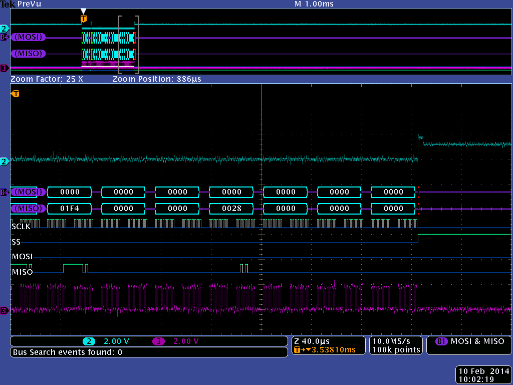
After configuring the C6657 EVM to SPI-Boot, i.e. SW3 = 1011 0000, and SW5 = 0010 0000, and booting the EVM I do witness it perform SPI reads of the specified 36 bytes, but the C6657's RBL does NOT issue any subsequent SPI reads from the specified Read Address of 0x00000024 provided within the SPI Boot Parameter Table above.

For completeness the following Boot Table has also been programmed into the NOR Flash immediately following the SPI Boot Parameter Table above.  This is the "simple" application provided by TI.

0x00810000 0x00000040 0x00810000 0x0099a228 0x00889168 0x010100a8 0x014000e8 0x01080226 0x01810828 0x01c000e8 0x018c3626 0x020c0226 0x0001a120 0x00000000 0x00000000 0x00000000 0x00000000 0x00000000 0x00000000 0x00000004 0x00810100 0x1234abcd 0x00000001 0x00810201 0x12000000 0x00000002 0x00810210 0x12340000 0x00000000

Again, I see the SPI Parameter Table being read, but no SPI reads are being requested to load the Boot Table.  Why?

I would appreciate any help to explain what is wrong within the SPI Parameter Table preventing the RBL from proceeding to load the Boot Table via SPI.

Is the KeyStone Architecture Bootloader User Guide (SPRUGY5B) correct?  If so, what is wrong?  If not, please advise updated documentation for the correct procedure to perform a direct SPI Boot from NOR Flash.

Thanks,

-George

  • Hi Arun

    I stil have a few questions that I hope you can answer.

    I managed to get the spiboot.c from the zip file compiled, linked and parsed through romparse, but when I call the byteswapccs I get an error that CYGWIN1.dll is not installed.

    So I installed CYGWIN 32 bit version, and added c:\cygwin to my PATH that helped.

    Shall I just use the romparse.exe that came with the zip file?

    How will I know if the output Works?

    which of the two bin files shall I flash to the NOR flash?

    Thanks

    Jens 


  • Hi Geroge, Arun,

    I was refered by multiple people to this E2E posting.   Thank you for laying the ground work for all C6657 EVM user.

    I following your procedure and generated spirom_le.swap.bin (attached)

    3146.spirom_le.swap.bin.txt
    (2E ��(��v�@���(��h�@�&�(���6&&� �4����4h�5A{l�bGz����O3x0q�U���ZZZZ####""""3333DDDDpLffff��������������������������������

    The RBL only reads

    0x00280000 0x00320000 0x45200002 0x00010018 0x00040000 0x00000000 0x03e80000 0x01f40000 0x00280000 0x00000000

    then stops.    Do you know why?

    Thank you.

    Regards,

    Steve

  • hi Arun, hi George,

    thank you for all the work and information.

    As I am pretty new to the EVM C6657 and SPI boot, lots of the topics were confusing to me.

    Q1: I just would like to boot an example from NOR flash on my C6657 EVM via SPI (without IBL). What .zip file have linked so far, would you recommend?

    Q2: When using the the norwriter-project to burn the flash: which start_addr should I set in "nor_writer_input.txt" and which file (.bin or .dat) in your .zip should I load to 0x80000000 before flashing?

    Thanks+Regards. Gregor

  • I forgot Q3: How do you debug the the booting process? You said that you can see what the RBL is doing. So far, I do not know what is going on after I turn on power. I just see that see no LED blink (TI example with bugeous romparse).

    Thanks.

  • ok, I could solve Q1 and Q3 now.

  • Hi GregorS,

    For Q2, you can refer to the Readme.txt file provided under tools/writer/nor/docs in MCSDK 2.x. The start_addr is the address on the NOR flash from which the device boot the boot image. By default this is set to 0 but if you modify the start_addr from which the image needs to be loaded then you can write the image to that address in the .txt file. As a rule, this address should always be start byte address of a sector on the NOR flash.

    Regards,

    Rahul

  • Hi SCQ,

    Did you read the Program counter when the boot fails after the initial reads. The program counter can help s identify the ROM function that the boot fails in. Also please provide details on what boot image you are using and how you have created the boot image.

    Regards,

    Rahul

  • Hi SCQ,

    Did you read the Program counter when the boot fails after the initial reads. The program counter can help us identify the ROM function that the boot fails in. Also please provide details on what boot image you are using and how you have created the boot image.

    Regards,

    Rahul

  • Hi Rahul,

    The PC is at 0x20B0EB90 when boot fails.  It is running in a loop around there.

    I am attaching the app.bin file which is programmed in the NOR FLASH.

    4657.app.bin.txt
    (2E�2(��v�@���(��h�@�&�(���6&&� �4����4h�5A{l�bGz����O3x0q�U���ZZZZ####""""3333DDDDpLffff��������������������������������

    Since I cannot attach a .bin file, I renamed it to app.bin.txt.

    The following are the PC after boot failed.

    Thanks.

    Steve


  • hi Rahul and Steve,

    how do you debug the booting process? Do you have some "RBL.out" which you could load on the DSP and then step through? 

    I am interested in seeing how the RBL is reading the words from NOR flash as I want to replace the NOR Flash on my own board by an other memory and need to know in which "style" (ordering, special fill words etc) the NOR Flash is providing the boot image to the RBL at the EVM.

    Thanks+Regards, Gregor

  • Hi Arun,

    I have an SPI boot problem with TMDSEVM6657LS too.  The RBL only reads the high lighted bytes then stops.

    What might be the problem.  Thanks.  Steve

  • Gregor,

    We have released the source code to the C6657 ROM on the web that you can refer to in order to understand how the NOR flash is performed. I have provided a link to the RBL source below:

    http://software-dl.ti.com/sdoemb/sdoemb_public_sw/rbl/1_0_C6657/index_FDS.html  

    We also provide a debug GEL file, that helps to ensure that the device is configured as required on by the boot image

    http://processors.wiki.ti.com/index.php/Keystone_Device_Architecture 

    I looked at the PC value that you had reported and it does appear that the RBL is stalled in the hardware SPI transfer function in the code. 

    Regards,

    Rahul

  • Hi Gregor,

    I am attaching an sample bootimage that I am able to boot on the C6657 EVM without the IBL.  Please refer to the document that I have attached and use the boot image provided to confirm that you are able to boot the example on the EVM.

    1452.Booting_from_SPI NOR_C6678.pdf

    2845.SPI_Bootloader.zip

    While setting the boot switches for the EVM, please refer to the ROM SPI boot setting mentioned on the wiki instead of the document.

    http://processors.wiki.ti.com/index.php/TMDSEVM6657L_EVM_Hardware_Setup 

    Please let us know

    Regards,

    Rahul

  • Rahul,

    I am Steve, not Gregor.  Please take a look at my SPI boot problem with TMDSEVM6657LS.

    I programmed the following file to the FLASH.  But by observing from oscilloscope, RBL only reads the first 40 bytes (highlighted), then stops.  What is the problem? 

    Thanks.

    Steve

  • Hi Steve,

    I see no issues with the application binary file that you have created. Did you look at the SPI chip select when the boot stops. Is it possible to get a scope shot that shows the chip select when the boot stops. Have you eliminated any hardware issue causing this boot stall. Did the example I provided also result in the same issue.

    Regards,

    Rahul

    PS: sorry for the delay in getting to this issue. Tracking threads that are already marked answered is difficult so I would recommend that you start a new thread for future issues.

  • Hi Rahul,

    Thanks for the reply.  I am looking into the SPI chip select and found it is about one volt, too low?

    I did not receive your example.   In your previous post, the two links about RBL are not valid.

    Thanks.

    Steve

  • Hi Rahul,

    We are using external FLASH for this EVM.   From TI support, we modified my TMDSEVM6657LS according to attached document to bring SPI chip selection to TEST_PH1 header, pin 41(DSP_EMIFCE2Z.0451.DOC001.PDF

    Thank you.

    Steve

  • Can you provide the map file for your binary,  I want to check if the out file is using any memory region that may be reserved by the RBL? Have you changed the values in the boot parameter table  for SPI boot ? If yes, can you provide the modified parameter table. One reason for this could be that the first 40 bytes of the boot image read in parameter table values that configures the device PLL which inturn causes the boot to stall after the parameter table is read in.

    Regards,

    Rahul

  • Hi Rahul,

    Here are the files.

    8306.simple.map.txt
    ******************************************************************************
                   TMS320C6x Linker PC v7.4.2                      
    ******************************************************************************
    >> Linked Mon Feb 10 09:38:25 2014
    
    OUTPUT FILE NAME:   <simple.out>
    ENTRY POINT SYMBOL: "_c_int00"  address: 80010000
    
    
    MEMORY CONFIGURATION
    
             name            origin    length      used     unused   attr    fill
    ----------------------  --------  ---------  --------  --------  ----  --------
    PAGE 0:
      DDRCFG                00873500   00000100  00000068  00000098  RWIX
    
    PAGE 1:
      TEXT                  80010000   00000040  00000040  00000000  RWIX
      DATA                  80010100   00000004  00000004  00000000  RWIX
      BYTE1                 80010201   00000001  00000001  00000000  RWIX
      BYTE2                 80010210   00000002  00000002  00000000  RWIX
    
    
    SECTION ALLOCATION MAP
    
     output                                  attributes/
    section   page    origin      length       input sections
    --------  ----  ----------  ----------   ----------------
    .ddrCfg    0    00873500    00000068     
                      00873500    00000068     ddrcfg.obj (.ddrCfg)
    
    .text      1    80010000    00000040     
                      80010000    00000040     simple.obj (.text)
    
    .data      1    80010100    00000004     
                      80010100    00000004     simple.obj (.data)
    
    .byte1     1    80010201    00000001     
                      80010201    00000001     simple.obj (.byte1)
    
    .byte2     1    80010210    00000002     
                      80010210    00000002     simple.obj (.byte2)
    
    
    GLOBAL SYMBOLS: SORTED ALPHABETICALLY BY Name 
    
    address    name
    --------   ----
    00000000   $bss
    80010100   .data
    80010000   .text
    0087355c   EccAddrRange1
    00873560   EccAddrRange2
    00873558   EccCtrl
    00873500   EnableBitmap
    00873528   IODFT_TLGC
    00873538   IrqEnable
    00873550   MtrIdClassMap1
    00873554   MtrIdClassMap2
    00873520   NVMTiming
    0087352c   PerfCtrCfg
    00873530   PerfCtrSel
    00873544   PhyCtrl1
    00873548   PhyCtrl2
    00873504   PllCfg
    00873524   PowerMgmt
    0087354c   PriClassMap
    00873534   RdIdleCtl
    00873564   RwExcThresh
    00873508   SDRAMConfig
    0087350c   SDRAMConfig2
    00873510   SDRAMRefreshCtl
    00873514   SDRAMTiming1
    00873518   SDRAMTiming2
    0087351c   SDRAMTiming3
    00873540   TempAlertCfg
    0087353c   ZqCfg
    ffffffff   ___TI_pprof_out_hndl
    ffffffff   ___TI_prof_data_size
    ffffffff   ___TI_prof_data_start
    ffffffff   ___binit__
    ffffffff   ___c_args__
    ffffffff   ___cinit__
    80010100   ___data__
    80010104   ___edata__
    80010040   ___etext__
    ffffffff   ___pinit__
    80010000   ___text__
    80010000   _c_int00
    ffffffff   binit
    80010201   byte1
    80010210   byte2
    ffffffff   cinit
    80010104   edata
    80010040   etext
    ffffffff   pinit
    80010100   someData
    
    
    GLOBAL SYMBOLS: SORTED BY Symbol Address 
    
    address    name
    --------   ----
    00000000   $bss
    00873500   EnableBitmap
    00873504   PllCfg
    00873508   SDRAMConfig
    0087350c   SDRAMConfig2
    00873510   SDRAMRefreshCtl
    00873514   SDRAMTiming1
    00873518   SDRAMTiming2
    0087351c   SDRAMTiming3
    00873520   NVMTiming
    00873524   PowerMgmt
    00873528   IODFT_TLGC
    0087352c   PerfCtrCfg
    00873530   PerfCtrSel
    00873534   RdIdleCtl
    00873538   IrqEnable
    0087353c   ZqCfg
    00873540   TempAlertCfg
    00873544   PhyCtrl1
    00873548   PhyCtrl2
    0087354c   PriClassMap
    00873550   MtrIdClassMap1
    00873554   MtrIdClassMap2
    00873558   EccCtrl
    0087355c   EccAddrRange1
    00873560   EccAddrRange2
    00873564   RwExcThresh
    80010000   .text
    80010000   ___text__
    80010000   _c_int00
    80010040   ___etext__
    80010040   etext
    80010100   .data
    80010100   ___data__
    80010100   someData
    80010104   ___edata__
    80010104   edata
    80010201   byte1
    80010210   byte2
    ffffffff   ___TI_pprof_out_hndl
    ffffffff   ___TI_prof_data_size
    ffffffff   ___TI_prof_data_start
    ffffffff   ___binit__
    ffffffff   ___c_args__
    ffffffff   ___cinit__
    ffffffff   ___pinit__
    ffffffff   binit
    ffffffff   cinit
    ffffffff   pinit
    
    [49 symbols]
    

    1030.mySpiBoot.map.txt
    section {
     boot_mode = 50
     param_index = 0
     options = 1
     core_freq_mhz = 1000
     next_dev_addr_ext = 0x0
     sw_pll_flags = 1
     sw_pll_mult = 32
     sw_pll_prediv = 5
     sw_pll_postdiv = 2
     addr_width = 24
     n_pins = 4
     csel = 0
     mode = 0
     c2t_delay = 0
     bus_freq_mhz = 500
     bus_freq_khz = 0
     exe_file = "mySpiBoot.btbl.bcv64x.i2c.ccs"
    }
    

    Thanks.

    Regards,

    Steve

  • Rahul,

    Thanks for the post with the example NOR boot application and document. I've been struggling days with this but was able to follow your instructions and make it work, at least with your example application.

    I have a follow-up question. How would I go about making a similar app that runs from DDR? I noticed when I booted your led_play app then connected CCS, the DDR is not configured.

    That might be a dumb question but even though I was able to follow your step-by-step instructions, I still don't really understand how the whole process works and what those steps actually did. The regular documentation has me really confused.

  • I think this wiki page might be wrong regarding the SPI CPOL/CPHA settings.  If I use these settings, I see the the MISO change on the rising edge and the MOSI change on the falling edge (or maybe it's the other away around--anyway, they're different than each other).

    Likewise, having the "mode" field be 0 in the romparse input table will also cause this issue.  mode = 1 causes both devices to change on the same (falling) edge.

    John

  • Hi Steve,

    I was out of office for a few days but will look at your map file and SPI settings and give you my inputs by end of the day today.

    Regards,

    Rahul

  • Thanks. 

  • For your easy track, I opened a new thread for this.

    http://e2e.ti.com/support/dsp/c6000_multi-core_dsps/f/639/t/321577.aspx

  • Hi,

    Is the above post with the example NOR boot application 2845.SPI_Bootloader.zip for C6657 EVM? If it's for C6657 then what's hardware switch setting to make it work? I am confused because the document is for C6670/C6678. And the TMDSEVM6657L_EVM_Hardware_Setup link is broken. I programm led_play.dat into flash and use SPI boot setting SPI-Boot, i.e. SW3 = 1011 0000, and SW5 = 0010 0000. After cycling the power,  there are some SPI activities but I am not seeing any led flashing. I also try loading led_play.out with jtag and run, it stop w/ message" abort() at exit.c:1090x0C04F000 (abort does not contain frame information).

    If led_play.dat is for C6657 EVM, please clarify how to configure the board to made it work. If it's not for C6657, then please provided one example so that I can I can test it to make sure my EVM board is configured correctly for dirrect SPI boot.

    Thanks,

    GanZ

  • Hi Ganz,

    Please look at the SPI DDR example that i have posted on the following e2e post.

    http://e2e.ti.com/support/dsp/c6000_multi-core_dsps/f/639/t/321577.aspx

    There is a ReadMe text in the attachment that describes how to boot the image. There is a typo in the readMe that refers to the norwriter as nandwriter so please make sur eyou program the EVM using the norwriter in the MCSDK.

    Setup the EVM using the boot switch settings described in here :

    http://processors.wiki.ti.com/index.php/TMDSEVM6657L_EVM_Hardware_Setup

    If you rebuild the example you need to change the value at offset 0x1F from 51 to 0x00 manually. Let us know if you have any issues replicating this example on your EVM.

    Regards,

    Rahul

  • Thanks Rahul,

    I am able to replicate the SPI DDR example on my EVM.

    GanZ.

  • now I face the similar problem .I observe from the oscilloscope that the dsp send 03 00 00 00 and read from the flash the same data 1651 in the .dat file ,the first data of the first line in the file ,why you directly jump to the offset adress 28 ,do you have the same first line (1651 1 10000 1 1dc7)in the .dat file ?