This thread has been locked.

If you have a related question, please click the "Ask a related question" button in the top right corner. The newly created question will be automatically linked to this question.

The LTSSM_STATE is always 0x2 after the PC reset.

Other Parts Discussed in Thread: TMS320C6670

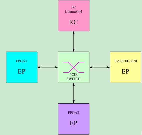
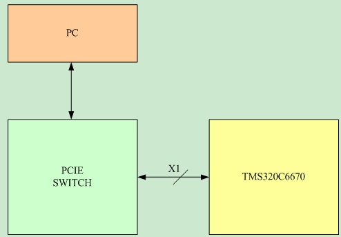
I have designed a PCB board by using TMS320C6670. The PCIE link architecture is showed in figure 1.

                                                             Figure 1


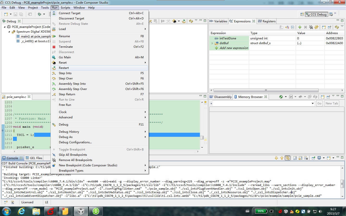
I use the PCIE_exampleProject to test the PCIE interface of the TMS320C6670. Because the PCIE link will break down, so I add some codes to monitor the value of the LTSSM_STATE in register DEBUG0. If LTSSM_STATE != 0x11, rebegin to link training by set LTSSM_EN = 1;


I reset the PC to test the PCIE link, the link is ok at the first two reset. But when I thirdly reset the PC, the LTSSM_STATE will always be 0x2.


Why? 

Thank you!

  • Xiang,

    When you re-initialize the PCIe link training on the C6670, will the PC try to do the same thing as well? 

    Will there be any chance the PC will stop the link training before the C6670 start the link training please?

    And what is the status of the PCIe switch please? Is it always powered up and being transparent between C6670 and PC during the testing?

    Another thing to note is the PCIe link state machine (LTSSM) will change to other states as well, such as Recovery.Config (LTSSM_STATE = 0x0F) or L0s (LTSSM_STATE=0x12). They are not equal to L0 (0x11) but they are not necessarily means the link is down for good. 

    The PCIe could recover from the Recovery mode or from the power saving mode (L0s) to the normal operation mode L0 automatically in most of the time. 

    So instead of keeping monitoring the DEBUG0 register, you could setup the link down interrupt request on PCIe module to trigger an interrupt to the C6670 if the PCIe link is down. 

    There is one example attached in the following thread. It is done based on the PCIe PDK example as well, but in the RC to EP scenario.

    You can take a look at the interrupt setup to see if it is useful in your case.

    http://e2e.ti.com/support/dsp/c6000_multi-core_dsps/f/639/p/245625/864695.aspx#864695

  • The actual topology architecture of the PCIE is showed as figure 2. In order to simplify it, I did not finger out the other PCIE devices.

    The PCIE Switch device has the ability to attempt to re-link the PCIE port, and each PCIE port with a led to indicate if the port link is ok or not. After the RC is reset, the port of FPGA1 and FPGA2 are always OK each time. But the port of TMS320C6670 will not OK after reset the RC two times.

    The PCIE Switch device is transparent between the RC and each EP device. When the port of TMS320C6670 is not OK, I check the LSSM_STATE of register DEBUG0, the value of it is 0x02 or 0x06.

    The codes I added in the PCIE_exampleProject is as follow:

    -----------------------------------------------------------------------------------------------------

    while(1) {

    cycleDelay(100);

    getRegs.debug0 = &debug0;

    if (Pcie_readRegs (handle, pcie_LOCATION_LOCAL, &getRegs) != pcie_RET_OK) {

    System_printf ("Read LTSSM state failed!\n");

    return;

    }


    ltssmState = debug0.ltssmState;

    if(ltssmState != pcie_LTSSM_L0)

    {

    /* Configure SERDES*/

    if ((retVal = pcieSerdesCfg()) != pcie_RET_OK) {

    System_printf ("PCIe Serdes config failed (%d)\n", (int)retVal);

    exit(1);

    }


    /* Set the PCIe mode*/

    if ((retVal = Pcie_setMode(PcieModeGbl)) != pcie_RET_OK) {

    System_printf ("Set PCIe Mode failed (%d)\n", (int)retVal);

    exit(1);

    }


    /* Power up PCIe Module */

    if ((retVal = pciePowerCfg()) != pcie_RET_OK) {

    System_printf ("PCIe Power Up failed (%d)\n", (int)retVal);

    exit(1);

    }


    System_printf ("PCIe Power Up.\n");


    /* Wait until the PCIe SERDES PLL locks */

    while (!lock) {

    CSL_BootCfgGetPCIEPLLLock(&lock);

    }


    if ((retVal = Pcie_open(0, &handle)) != pcie_RET_OK) {

    System_printf ("Open failed (%d)\n", (int)retVal);

    exit(1);

    }

    System_printf ("PLL configured.\n");


    /* Configure application registers for End Point*/

    if ((retVal = pcieCfgEP(handle)) != pcie_RET_OK) {

    System_printf ("Failed to configure PCIe in EP mode (%d)\n", (int)retVal);

    exit(1);

    }


    /* Configure Address Translation */

    barCfg.location = pcie_LOCATION_LOCAL;

    barCfg.mode     = pcie_EP_MODE;

    barCfg.base     = PCIE_IB_LO_ADDR_S;

    barCfg.prefetch = pcie_BAR_NON_PREF;

    barCfg.type     = pcie_BAR_TYPE32;

    barCfg.memSpace = pcie_BAR_MEM_MEM;

    barCfg.idx      = PCIE_BAR_IDX_S;


    if ((retVal = Pcie_cfgBar(handle, &barCfg)) != pcie_RET_OK) {

    System_printf ("Failed to configure BAR!\n");

    exit(1);

    }


    ibCfg.ibBar = PCIE_BAR_IDX_S; /* Match BAR that was configured above*/

    ibCfg.ibStartAddrLo = PCIE_IB_LO_ADDR_S;

    ibCfg.ibStartAddrHi = PCIE_IB_HI_ADDR_S;

    ibCfg.ibOffsetAddr  = (uint32_t)pcieConvert_CoreLocal2GlobalAddr ((uint32_t)dstBuf.buf);

    ibCfg.region = PCIE_IB_REGION_S;


    if ((retVal = pcieIbTransCfg(handle, &ibCfg)) != pcie_RET_OK) {

    System_printf ("Failed to configure Inbound Translation!\n", (int)retVal);

    exit(1);

    }

    else{

    System_printf ("Successfully configured Inbound Translation!\n");

    }


    if ((retVal = pcieObTransCfg (handle, PCIE_OB_LO_ADDR_S, PCIE_OB_HI_ADDR_S, PCIE_OB_REGION_S)) != pcie_RET_OK) {

    System_printf ("Failed to configure Outbound Address Translation!\n", (int)retVal);

    exit(1);

    }

    else {

    System_printf ("Successfully configured Outbound Translation!\n");

    }


    System_printf ("Starting link training...\n");


    /*Enable link training*/

    if ((retVal = pcieLtssmCtrl(handle, TRUE)) != pcie_RET_OK) {

    System_printf ("Failed to Enable Link Training!\n", (int)retVal);

    exit(1);

    }


    /* Wait for link to be up */

    pcieWaitLinkUp(handle);


    System_printf ("Link is up.\n");

           }

    else{

    CSL_GPIO_setOutputData(hGpioDsp0, 1);

    led_delay(1000);

    CSL_GPIO_clearOutputData(hGpioDsp0, 1);

    led_delay(1000);

    }

    }

  • Xiang,

    Could you please add "pciePowerDownCfg()" before "pciePowerCfg()" as we discussed in the following thread please?

    http://e2e.ti.com/support/dsp/c6000_multi-core_dsps/f/639/p/248069/872435.aspx

    It is equivalent to reset the PCIe configuration registers, which may remove the residue of PCIe configurations from your last run.

  • Hi, Steven:


    Thank you for your help. Now with the pciePowerDownCfg() function, the PCIESS LINK is OK every time after the PC reset. But I am using the while(1){} architecture to check the LTSSM_STATE value of register DEBUG0.

           I use the code mentioned in http://e2e.ti.com/support/dsp/c6000_multi-core_dsps/f/639/p/245625/864695.aspx#864695, and I can see LINK_RST_REQ of register PMRST_IRQ_STATS is set to 1 when the PC reset. But the program does not go into the interrupt service routine.

           I am puzzled with some statement of the interrupt configure function.


    Question 1:

    intcContext.numEvtEntries      = 10;


    How to decide the value of intcContext.numEvtEntries?


    Question 2:

           vectId = CSL_INTC_VECTID_4;

    hTest = CSL_intcOpen (&intcObj, 56, &vectId , NULL);


    CSL_CPINTC_mapSystemIntrToChannel (hnd, 49, 40);


    I find that the event 56 is Interrupt Controller output on page 158 of TMS320C6670 datasheet (Table 7-38: System Event Mapping –C66x CorePac Primary Interrupts).


    And 49 is PCIEXpress_PM_INT event input on page 161 of TMS320C6670 datasheet (Table 7-39:CIC0 Event Input – C66x CorePac Secondary Inputs).


    But I don’t find why to set parameter 40? How to decide it?


    Thank you very much! 

  • Xiang,

    1. The "numEvtEntries" (number of event entries) corresponds to the number of events that the programmer plans to map. You can just choose a reasonable number that you plan to use in the interrupt mapping. It does not need to be 10 only.

    2. The example code was originally targeted for C6657 device, so you may need to use different event numbers if you want to port it to C6670.

    The system event 49 (PCIe_PM_INT) is still true as CIC0 input in C6670 and event 56 of CorePac INTC is CIC0_OUT0 in C6670 instead of CIC0_OUT40 in C6657.

    So in C6670, you can map system event 49 to CICI0_OUT0 first and then map CIC0_OUT0 (event 56) to CorePac INTC (VectID 4).

    You can use the following mapping with the other setup the same:

    CSL_CPINTC_mapSystemIntrToChannel (hnd, 49, 0);


  • hi, Steven:

    Thank you very much for your help. Now I can use interrupt to re-configure the PCIESS when the PC is reset. I am not familar with the CCS software, so when I set a break point in the interrupt service function and  run the program in CCS5.3 with "free run" operation mode, but it is seemed that the CCS not capture the interrupt.

    If I want to observe the interrupt, how can I set in the CCS software?

    Thank you very much!

  • I think "free run" option in CCS will disable all the breakpoints and the debugger has no access to the device.

    Could you just try "Run" in CCS for your testing?

    You may find more details in CCS forum.

    http://e2e.ti.com/support/development_tools/code_composer_studio/default.aspx

  • I just find the "Free run" button, don't find the "run" button. 

  • It should be the "Resume (F8)" button on the menu.