This thread has been locked.
If you have a related question, please click the "Ask a related question" button in the top right corner. The newly created question will be automatically linked to this question.
Tool/software: TI-RTOS
Hello,
For OMAP-L138(DSP+ARM9) LCDK development kit,
I was referring schematic given on 'online technical document' which is same as schematic provided with board SD card.
But pin configuration is different as per given in schematic.
Can I get correct schematic?
ex,
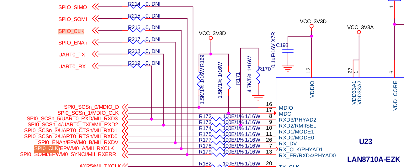
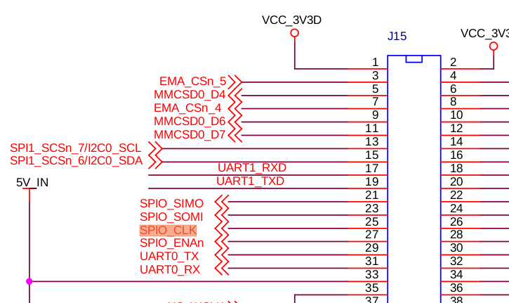
( SPI0_CLK actually is going to 'pin no 34' of J16
but On schematic, They gave as pin no 32 of J16
Same for SPI0_SIMO.)
Regards,
Kshitika
University of strathclyde, Glasgow
The schematic can be downloaded from here:
If you have a look SPI0_CLK goes to the ethernet phy:
If you remove R178 and populate R216 you will see that SPI0_CLK goes to SPIO_CLK, which is outputted on pin 25 of J15 (NOT J16):
Actually SPI1_CLK is outputted on J16 (which is the camera interface).
Best Regards,
Yordan
Yordan Kovachev said:The schematic can be downloaded from here:
TI: Sorry! We couldn't find your page.
The page you are looking for might have been removed, had its name changed, or is temporarily unavailable.If you have a look SPI0_CLK goes to the ethernet phy:
If you remove R178 and populate R216 you will see that SPI0_CLK goes to SPIO_CLK, which is outputted on pin 25 of J15 (NOT J16):
Actually SPI1_CLK is outputted on J16 (which is the camera interface).
Best Regards,
Yordan
Hello,
I am unable to follow above link to download correct schematic.
It says link is broken.
Regards,
Kshitika