This thread has been locked.

If you have a related question, please click the "Ask a related question" button in the top right corner. The newly created question will be automatically linked to this question.

Linux/AM4378: SPI flash issue

Part Number: AM4378
Other Parts Discussed in Thread: AM4372,

Tool/software: Linux

Hello,

I am use the AM4378-GP-EVM SPI 1 interface to connect Atmel SPI flash AT45DB161D. I am using Linux on the platform.  I can't read out the contents even for read flash manufacturing information command 0x9f. The readout are zeros. I am using the utility spidev_fdx privided with Ti Linux package.

Here is the SPI in device tree: (am437x-gp-evm.dts)

In &am437x_pinmux section:

spi1_pins: pinmux_spi1_pins {
                pinctrl-single,pins = <
                        AM4372_IOPAD(0x990, PIN_INPUT | MUX_MODE3)          /* spi1_clk */
                        AM4372_IOPAD(0x994, PIN_OUTPUT | MUX_MODE3)          /* spi1_d0 */
                        AM4372_IOPAD(0x998, PIN_INPUT | MUX_MODE3)           /* spi1_d1 */
                        AM4372_IOPAD(0x99c, PIN_OUTPUT | MUX_MODE3)          /* spi1_cs0 */
                >;
        };

spi1 node:

&spi1 {
        status = "okay";
        pinctrl-names = "default";
        pinctrl-0 = <&spi1_pins>;
        ti,spi-num-cs = <4>;
        ti,pindir-d0-out-d1-in;

        spidev@1 {
                reg = <0>;
                status = "okay";
                compatible = "rohm,dh2228fv";
                spi-max-frequency = <20000000>;
        };
};

In am4372.dts:

spi1: spi@481a0000 {
                        compatible = "ti,am4372-mcspi","ti,omap4-mcspi";
                        reg = <0x481a0000 0x400>;
                        interrupts = <GIC_SPI 125 IRQ_TYPE_LEVEL_HIGH>;
                        ti,hwmods = "spi1";
                        #address-cells = <1>;
                        #size-cells = <0>;
                        status = "okay";
                };

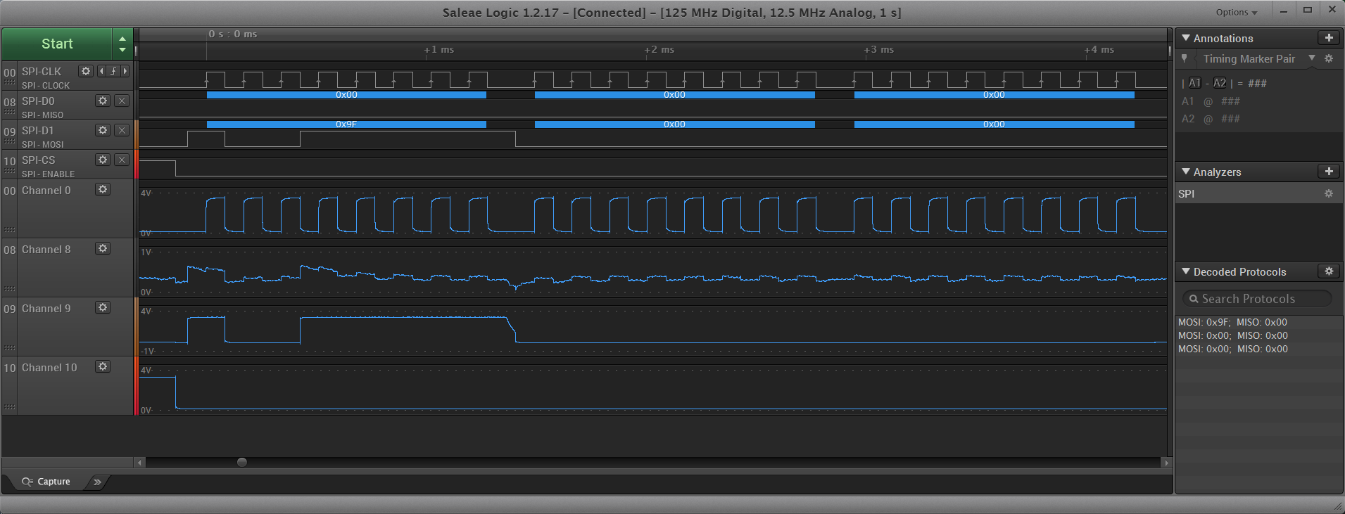
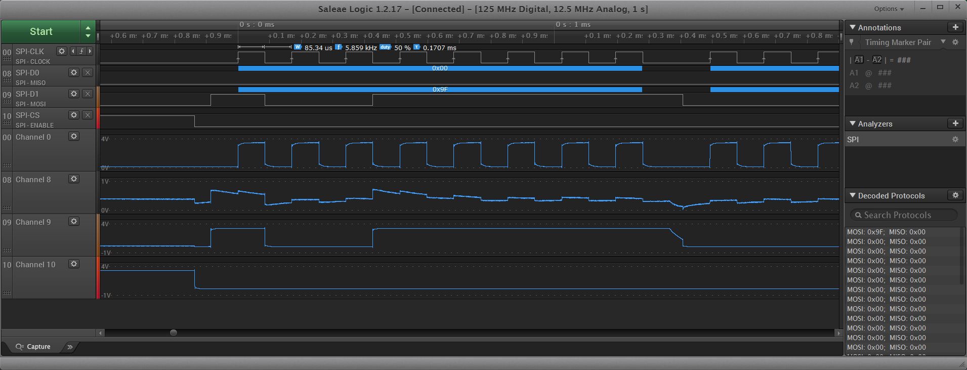
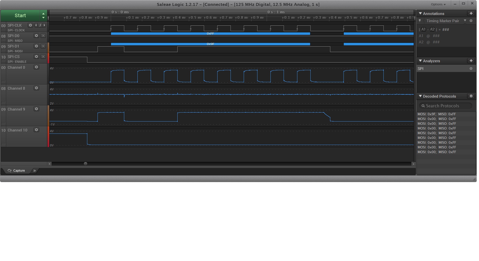
Here is the waveform I captured: (the first readout should be 0x1f)

All other commands are the same. Also I notice when I use the utility spidev_fdx or spidev_test the readouts are not stable when the read count is bigger than 159. (waveform also display all 0s).

Please help!

Thanks,

-Ken

  • Attached please find the wave form for read manufacturing id command.

  • Hi,

    What Linux version is this?
  • ti-processor-sdk-linux-am437x-evm-04.03.00.05
  • linux-4.9.69+gitAUTOINC+9ce43c71ae-g9ce43c71ae
  • This is my SPI support in kernel.


    ┌──────────────────────────────────────────────────────────────────────────────────────────────────────────────────────────────────────────────────────────────────────────────────┐ │
    │ │ --- SPI support │ │
    │ │ [*] Debug support for SPI drivers │ │
    │ │ *** SPI Master Controller Drivers *** │ │
    │ │ < > Altera SPI Controller │ │
    │ │ < > Analog Devices AXI SPI Engine controller │ │
    │ │ {M} Utilities for Bitbanging SPI masters │ │
    │ │ < > Cadence SPI controller │ │
    │ │ < > DesignWare SPI controller core support │ │
    │ │ <M> GPIO-based bitbanging SPI Master │ │
    │ │ < > Freescale SPI controller and Aeroflex Gaisler GRLIB SPI controller │ │
    │ │ < > OpenCores tiny SPI │ │
    │ │ < > PXA2xx SSP SPI master │ │
    │ │ < > Rockchip SPI controller driver │ │
    │ │ < > NXP SC18IS602/602B/603 I2C to SPI bridge │ │
    │ │ < > Analog Devices AD-FMCOMMS1-EBZ SPI-I2C-bridge driver │ │
    │ │ < > Xilinx SPI controller common module │ │
    │ │ < > Xilinx ZynqMP GQSPI controller │ │
    │ │ *** SPI Protocol Masters *** │ │
    │ │ <*> User mode SPI device driver support │ │
    │ │ <M> spi loopback test framework support │ │
    │ │ < > Infineon TLE62X0 (for power switching) │ │
    │ │ │ │
    │ │ │ │
    │ │
  • In config for your info:

    CONFIG_SPI=y
    CONFIG_SPI_DEBUG=y
    CONFIG_SPI_MASTER=y

    #
    # SPI Master Controller Drivers
    #
    # CONFIG_SPI_ALTERA is not set
    # CONFIG_SPI_AXI_SPI_ENGINE is not set
    CONFIG_SPI_BITBANG=m
    # CONFIG_SPI_CADENCE is not set
    # CONFIG_SPI_DESIGNWARE is not set
    CONFIG_SPI_GPIO=m
    # CONFIG_SPI_FSL_SPI is not set
    # CONFIG_SPI_OC_TINY is not set
    CONFIG_SPI_OMAP24XX=y
    CONFIG_SPI_TI_QSPI=y
    # CONFIG_SPI_PXA2XX is not set
    # CONFIG_SPI_PXA2XX_PCI is not set
    # CONFIG_SPI_ROCKCHIP is not set
    # CONFIG_SPI_SC18IS602 is not set
    # CONFIG_SPI_XCOMM is not set
    # CONFIG_SPI_XILINX is not set
    # CONFIG_SPI_ZYNQMP_GQSPI is not set

    #
    # SPI Protocol Masters
    #
    CONFIG_SPI_SPIDEV=y
    CONFIG_SPI_LOOPBACK_TEST=m
    # CONFIG_SPI_TLE62X0 is not set
    CONFIG_SPMI=y
    # CONFIG_HSI is not set
  • Please help. This is very urgent. Thank you very much in advance.
  • My connection:

    TI CLK -> Flash CLK
    TI CS -> Flash CS
    TI D0 -> Flash SI
    TI D1 -> Flash SO
  • I see two instances of each signal (i.e. " SPI-CLK/Channel 0", "SPI-D0/Channel 8". Please describe the test points on the PCB from where each waveform signal was captured. My initial feedback is you've properly set up the SPI in the DTS and linux kernel, because valid CLK, CS, and MOSI data can be seen from the waveform. However, the MISO should show a logic level 0, yet some signal is being transmitted on the MISO line, which could be interfering with the host state machine. First try eliminating the noise observed from the waveform and confirm the flash devices is 1) powered 2) initialized and 3) working properly.
  • Replay To Marcus:
    The two instance is for digital and analog captures for the same signal. This is the function of the logic analyzer. The signals are captured from the herder J30 pin 14 clk, pin 16 D0, pin 18 D1 and pin 20 cs.

    It seems like a lot of noise on the wire D0 on the analog capture. I have no idea about it. The flash is powered, reset correctly.

    Any possibility that can cause the noise on MISO? from the PCB or from the flash?

    Any suggestions are appreciate. Thanks you.
  • We would need a snippet of you schematic and h/e design files to provide the necessary guidance.
  • Memory_AT45DB161D.pdfThank you for your reply. As matter of fact we don't have any schematics at this moment. We use a off-shelf Integrated Biometics fingerprint sensor. We need to read the flash memory on the sensor. The SPI connection is via spi1 signals on J30 of the TI am437x-gp-evm. The flash on the sensor is Atmel AT45DB161D (datasheet attached).

    The connection:

    TI J30 CLK -> Flash CLK

    TI J30 CS -> Flash CS

    TI J30 D0 -> Flash SI

    TI J30 D1 -> Flash SO

    Thanks.

  • Do you see similar noise when the Biometrics fingerprint sensor is disconnected from the am437x-gp-evm?
  • Yes. I removed the fingerprint sensor and I tested spi 1 using spidev_fdx utility I still see the noise on MOSI. See attached waveform.

    Thanks,

    Ken

  • Hi Ken,
    The scale on the MISO signal appears to be between 0 and 1V compared to the 0 to 4V for the rest of these signals. It appears to me that the signal may be floating and that the noise is just other signals coupling onto the undriven line. Can you put a pull up resistor on the line to see if it is floating? I don't see any issue with the signals that are provided by the AM4378. Did you check the RDY/BUSY line from the device to see if it is attempting to delay the read?
    Regards, Bill
  • I change the config in the device tree for D1 as PIN_NPUT_PULLUP | MUX_MODE3 and testing now. There is no BUSY/RDY signal from the flash memory so I can't do any probe for that. The flash has sync timing for its commands. I will report back when I finish my spi test.

    Thanks,

    Ken

  • Hi Ken,
    The internal pull may not be enough for a signal driven through a cable. See what the results look like but you may have to add a real pull up resistor.
    Regards, Bill
  • the result: MOSI now keeps all high. The test utility read as all FFh. We use a very short like 4 inch wire for it.
  • Hi Ken,
    Was it a steady high without all the chatter on the line? As I suspected, the data line output from the memory is just floating. That means the memory device is not accepting the command and driving the device information. It appears that the AM4378 is operating correctly. You will have to investigate the connection to the memory and check to see if it is correct. Check the memory power as well. You might want to probe the clock at the memory device to make sure you are not seeing any ringing or reflections. That might cause a false clock detection inside the memory.
    Regards, Bill
  • Thank you. A last question before I will close this one as "solved":
    Is these pin configs ok? clk should be output? (I tried output, no help). no pullup or pulldown needed for all SPI1 signals for AM4378?

    AM4372_IOPAD(0x990, PIN_INPUT | MUX_MODE3) /* spi1_clk */
    AM4372_IOPAD(0x994, PIN_OUTPUT | MUX_MODE3) /* spi1_d0 */
    AM4372_IOPAD(0x998, PIN_INPUT_PULLUP | MUX_MODE3) /* spi1_d1 */
    AM4372_IOPAD(0x99c, PIN_OUTPUT | MUX_MODE3) /* spi1_cs0 */
  • The flash memory is 2.5 or 2.7 V. Do you think we can interconnect the signals with AM4378 SPI signals. with any voltage converter/shifter? (AM4378 is SPI 1 interface use VDDSHV 3.3 v?)
    Thanks,
    Ken
  • Correction:

    The flash memory is 2.5 or 2.7 V. Do you think we can interconnect the signals with AM4378 SPI signals without any voltage converter/shifter? (AM4378 is SPI 1 interface use VDDSHV 3.3 v?)
    Thanks,
    Ken
  • Ken,
    Your pin config looks correct to me. The data manual for the memory says it can operate from 2.5V to 3.6V. The IO voltage will be set but the voltage present on the VCC pin for the memory. Did you measure it at 2.5V?
    Bill
  • As matter of fact we apply 3.3 v for the flash VCC through a external power supply. I measure it is 3.3 v.
  • The SPI1 configuration and waveform are correct. So we can stop here for this topic. Another thing I mentioned in my original request is: when I use the utility spidev_fdx or spidev_test the readouts are not stable when the read count is bigger than 159.
    When I run:
    ./spidev_fdx /dev/spidev1.0 -m 159
    /dev/spidev1.0: spi mode 0x0, 8 bits (msb first) per word, 20000000 Hz max
    response(159, 167):
    ff ff ff ff ff ff ff ff ff ff ff ff ff ff ff ff ff ff ff ff ff ff ff ff ff ff ff ff ff ff ff ff
    ff ff ff ff ff ff ff ff ff ff ff ff ff ff ff ff ff ff ff ff ff ff ff ff ff ff ff ff ff ff ff ff
    ff ff ff ff ff ff ff ff ff ff ff ff ff ff ff ff ff ff ff ff ff ff ff ff ff ff ff ff ff ff ff ff
    ff ff ff ff ff ff ff ff ff ff ff ff ff ff ff ff ff ff ff ff ff ff ff ff ff ff ff ff ff ff ff ff
    ff ff ff ff ff ff ff ff ff ff ff ff ff ff ff ff ff ff ff ff ff ff ff ff ff ff ff ff ff ff ff

    When I run:
    ./spidev_fdx /dev/spidev1.0 -m 160
    /dev/spidev1.0: spi mode 0x0, 8 bits (msb first) per word, 20000000 Hz max
    response(160, 168):
    ff ff ff ff ff ff ff 20 20 20 52 65 63 65 69 76 65 20 20 20 20 20 20 20 20 20 20 20 20 20 20 20
    ff ff ff ff ff ff ff ff ff ff ff ff ff ff ff ff ff ff ff ff ff ff ff ff ff ff ff ff ff ff ff ff
    ff ff ff ff ff 72 61 6e 73 6d 69 74 0a 20 66 61 63 65 20 7c 62 79 74 65 73 20 20 20 20 70 61 63
    6b 65 74 73 20 65 72 72 73 20 64 72 6f 70 20 66 69 66 6f 20 66 72 61 6d 65 20 63 6f 6d 70 72 65
    73 73 65 64 20 6d 75 6c 74 69 63 61 73 74 7c 62 79 74 65 73 20 20 20 20 70 61 63 6b 65 74 73 20

    (The output is not stable. Even the first 159 bytes are changed)

    Thanks,

    Ken
  • When I run: ./spidev_fdx /dev/spidev1.0 -m 160 the waveform still shows all "ff" readouts.
  • Hi Ken,
    Did you make any progress? Have you tried any other SPI devices?
    Regards, Bill
  • Thanks Tabloada. The SPI now works for small amount of data read less than 160 bytes. But if the data read for spedev_fdx utility is bigger than 160 bytes the data in not correct even for the first 160 bytes, Feels like spidev_fdx utility provided by TI is not working with bigger amount data read. The same thing for the utility spidev_test. Is this a limitation in the spidev driver?

    Thanks,

    -Ken

  • The SPI driver will switch to DMA mode when data size is > 160. The issue you are reporting could be related to the following post

    e2e.ti.com/.../2659264

    Try applying the patches referenced in this post and retest.
  • Thanks you. This is good to try. I will report back.

    Ken
  • The patch is good. I still keep use the original 160 byte DMA limit since I just transfer small amount of data or use segment for large amount of data. The SPI operation is one-time operation at the application initialization.

    Thanks,

    Ken