This thread has been locked.
If you have a related question, please click the "Ask a related question" button in the top right corner. The newly created question will be automatically linked to this question.
Hi all,
At the moment we are using a AM3351 CPU in our design and we are connecting an eMMC memory device to the MMC1 port of the AM3351 (we do not boot from this device) the eMMC device and interface are powered by +3V3.
Now from timing analyses and measurements I noticed a timing issue in high speed mode on the hold timing between of the input on the CPU side and output hold at the eMMC memory. Potentially the eMMC already change its data output while the CPU still expects data to be valid.
The AM3351BZCEA30R supports according to the datasheet up to MMC4.3. We have connected an ISSI eMMC device (IS21ES04G) which complies to MMC5.0. Because both devices support HS mode this should be compatible with each other.
Input timing specification from the AM3351 (datasheet SPRS717J):
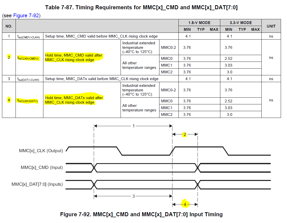
The eMMC HS timing specification:
From TI FAE I got information that the problem in my design it the MMC version. But I looked into JEDEC 4.3 and 5.0 and I don't see HS mode timing differences which would solve my problem. (This was before I posted my question online on E2E.)
So my question is, is this a known issue or do I overlook something in my analysis? Additionally how should I coupe with this issue if I didn't overlook something? (Of course there is the standard mode to solve this but we also lose half the speed which is of course not preferred at all.)
Thank you.
F. Veger
I do not think you are considering the delay inserted by your PCB traces. This type of timing analysis should be done before designing a PCB where timing adjustments are applied via delays in signal traces.
In this case, the worst case minimum hold time for the MMC1 DAT and CMD inputs for a AM3351 device is 3.76ns and the minimum output delay from the eMMC device operating in high speed mode should be 2.5ns. This would create hold time violation of 1.26ns if the combined PCB trace delays for the “processor to eMMC device for CLK signal” and “eMMC device to processor for DAT and CMD signals” were 0ns. However, this is not practical. Your PCB should have been designed with a combined delay for these two signal paths to be greater than 1.26ns. If so, this would have prevented a hold time violation to the processor DAT and CMD inputs.
Regards,
Paul
Hi Paul,
Thank you for the information. I agree on the fact we do have an physical delay in the traces.
First I was wondering about the worst case hold time. We are using MMC0 and 1 with the AM3351 which has a temperature range of -40 to 105 degC.
So is it correct to use the "All other temperature ranges" which gives lower requirements for MMC0 - 2.52ns and MMC1 - 3.03ns?
When using the worst case (1.26ns) required hold timing we need a trace length of at least 18cm (using 70ps/cm), so 9.5cm at least of trace length in-between the CPU and eMMC device is what you mean if I'm not mistaken?
Regards,
Francois.
The distance required will vary slightly based on propagation delay in your PCB design. Using a approximate delay of 167ps per inch for FR4 based PCBs, I got a value of 9.6cm. So you should be okay with this distance unless your PCB has much faster propagation delay than typical PCBs.
Regards,
Paul