This thread has been locked.

If you have a related question, please click the "Ask a related question" button in the top right corner. The newly created question will be automatically linked to this question.

TDA4VM: How does TDA4 connect to Ultrasonic Sensors of IO interface?

Part Number: TDA4VM

The Ultrasonic Sensors(USS) are used for APA and AVP.

The Ultrasonic Sensors use ELMOS IC E524.09 as interface IC.

The interface of USS has only one signal line for input and output, we call this interface the IO interface.

We call this USS as the IO interface USS.

When connecting this USS to MCU, we select the PIN with PWM or timer function, because we want to send an impulse to trigger the USS and then perform time-dependent calculation on the received signal such as delay.

So, how does TDA4 connect to this USS? Is it OK to use PWM pin? Or do we have to use the timer pin?

Thanks.

  • Hello, 

    Without knowing the pulse width and receive signal characteristics of the USS interface pin, my first question would be if GPIO can be an option?

    Reason I am saying is that PWM pins are output only, so you will have to flip the mux to GPI upon sending the pulse via PWM. This may be workable if you want a precise pulse shape that GPIO does not have the resolution. 

    I believe the GPIO may reach ~80MHz so will need to know the expected pulse width and resolution on the USS. 

    regards

    Jian 

  • Thanks for your reply.

    ELMOS524.09 in USS, its IO Interface (AC) - Electrical Parameters

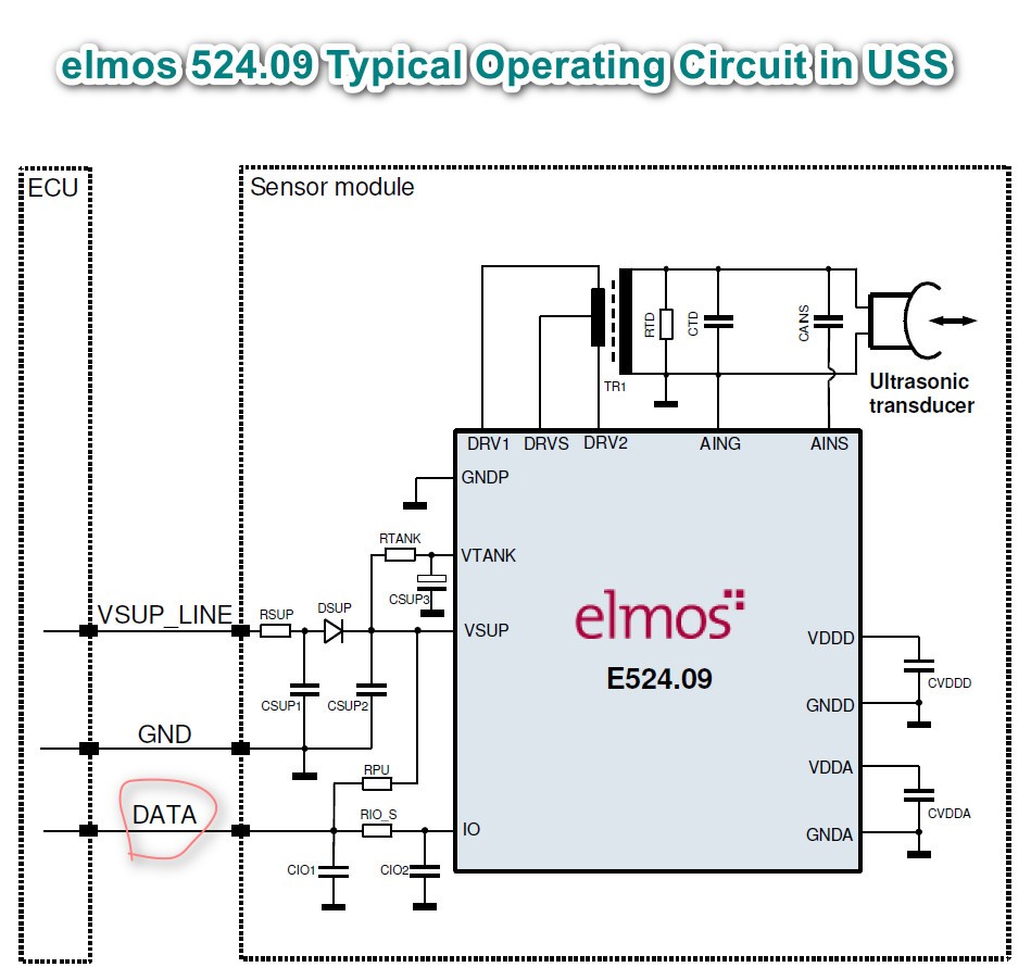
    elmos 524.09 Typical Operating Circuit in USS

  • Add more text description, which may be easier to understand than the chart in the previous post.

    First of all, the signal that TDA4 outputs to USS need to be a high level pulse around 50us, to let USS work.

    After that, the USS sends a signal, which is also about 50us wide. TDA4 gets the signal and measure the level width and level change to determine whether it is 1 or 0.

  • We use different PINs in TDA4 as TX and RX, although USS has only one IO line, the circuit is below.

    We think GPIO is OK as TX, the main question is the choice of RX pin in TDA4.

    Should we choose the TIMER IO pin or can the PWM pin be connected to the internal timer?

    The TIMER IO can measure the level width and level change of the input signal, is my understand right? Because we use MCU's TIMER input PIN to get the RX signal of USS, that is ok. 

    Because the number of TIMER IO is limited in TD4, we want to use some PWM pins. Can PWM pin achieve the same funciton as the TIMER IO input?

  • Hi, Hui:

    PWM is supposed to be used as output.

    If the TimerIO output PWM, the ePWM module can output similar PWM waveform.

    For Ultrasonic Sensors, the ECAP modules and GPTimers can be used to interface the RX (for TDA4VM). For TX, the ECAP/EPWM/GPTimers can all output PWM signals.