This thread has been locked.

If you have a related question, please click the "Ask a related question" button in the top right corner. The newly created question will be automatically linked to this question.

AFE7444EVM: AFE7444EVM initialize problem

Part Number: AFE7444EVM

Hi,TI support,

According to the AFE7422 and AFE7444 Programmer's Guide, I failed to initialize  AFE7444EVM using the SPI interface protocol.

The FPGA board I used is the ZC706 from Xilinx. I already know that when I use FMC to connect ZC706 to AFE7444EVM, I need to cut off the 5V power supply of 7444 and program the FMC interface voltage to 1.8V before burning the bit stream through Vivado.


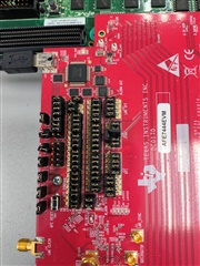
I want to know if my operation sequence is correct, and my  AFE7444EVM jumper is shown in the figure.

  • Hi Wanrui,

    Yes, the 5V power supply should be turned off while changing the FMC interface voltage to 1.8V. Once this change has been made you can supply the 5V power supply back to the EVM and then begin the programming sequence. One thing to note on your jumper settings is that you have the AFE SPI pins routed to the FMC connecter. Are you programming the AFE EVM from a FPGA through the FMC connector? If not then you would need to update the position of the J13 jumpers.

    Can you elaborate on the issue you see when you fail to initialize the AFE using SPI? 

    Regards,

    David Chaparro

  • Hi David,

    Yes, I programming the AFE EVM from a FPGA through the FMC connector.

    And I according to  the flowchart of the AFE7422 and AFE7444 Programmer's Guide, 

    Register addresses and values written through the SPIA interface are in hexadecimal format:

    [GPIO]
    W 0x0000 0x00,
    W 0x0000 0xB0,
    W 0x0011 0x08,
    W 0x0193 0x12,
    W 0x0194 0x12,
    W 0x0011 0x00,
    W 0x0011 0x10,
    W 0x0027 0x00,
    W 0x0028 0x00,
    W 0x0011 0x00,
    W 0x0011 0x08,
    W 0x0196 0x00,
    W 0x0190 0x00,
    W 0x0011 0x00,
    [e_fuse]
    W 0x0011 0x10,
    W 0x0021 0x01,
    W 0x004F 0x07,
    W 0x0023 0x01,
    W 0x0011 0x00,
    W 0x0011 0x08,
    W 0x00C6 0x00,
    W 0x00C6 0x01,
    W 0x00C6 0x00,
    R 0x00C2 0x0F,
    R 0x0170 0x00,
    R 0x0171 0x00,
    R 0x0172 0x00,
    R 0x0173 0x00,
    R 0x00BC 0x00,
    R 0x00BD 0x00,
    W 0x0011 0x00,
    W 0x0011 0x10,
    W 0x0023 0x00,
    W 0x0011 0x00,

    But I read the value of 0x00C2 as d60, not d15. I realized that the register addresses and values wrote are incorrect,But I don't know which register has the wrong value. Could you help me?

    Thank you,

    David

  • Hi Wanrui,

    If the e-fuse is not loading correctly then there are a couple of things that could be the cause.

    Please check the following:

    1. A stable clock should be provided to the AFE before the e-fuse loading. Has it been verified that the clock is seen at the AFE?

    2. All power should be stable. Please measure all power supplies at the AFE to verify they are within the limits.

    Regards,

    David Chaparro