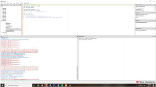
AFE7950EVM: AFE7950 qpll0 is not getting locked when configured through AFE79xx-Latte GUI

Part Number: AFE7950EVM

Tool/software:

Hi David,

This is in the response to the following locked thread: https://e2e.ti.com/support/rf-microwave-group/rf-microwave/f/rf-microwave-forum/1427050/afe7950evm-afe7950-qpll0-is-not-getting-locked-when-configured-through-afe79xx-latte-gui .

Apologies for the late reply. The "PLL2 Locked" LED is glowing; however, in chipscope, the qpll0_locked value does not change to 3 after deasserting master_reset_n. We have 2 key concerns; firstly, we want to confirm whether the glowing LED definitively indicates that PLL2 is locked, or could there still be an issue causing the problem in chipscope despite the LED being on? Additionally, since we are using the default script and provided files, are there any specific parameters we should check or modify to resolve this? Thank you for your assistance.

  • Hi,

    Yes, if the LED "PLL2 Locked" is on then indicates that the LMKs PLL2 has locked. Have you tried probing the FPGA clock at the LMK output to verify you see the right frequency? 

    Regards,

    David Chaparro 

  • Hi David,
    Thank you for your response.
    We have not found any direct probe point available to verify the LMK output clock. Could you kindly guide us regarding where on the board we can find the probe and any possible label it may have so that we can verify the frequency. Looking forward to your guidance.

  • Hi,

    On the EVM you can probe the pad of the series capacitor, C273 or C275, which are close to the LMK outputs. The image below is pointing to the location of the two caps next to the LMK on the bottom of the board. 

    Regards,

    David Chaparro 

  • Hi David,

    Thank you for your response. We have probed the 122.88 MHz crystal oscillator at R309 and the LMK clock near C275 (1474.56 MHz)  and are getting the correct LMK clock frequency albeit with very low power of -45.16dBm as shown below. Could you kindly tell us if this is the expected behaviour and if not, what could be causing such attenuation.

    We have also observed variation in the behaviour of the qpll locking with each power cycle. There are cases where the qpll locks immediately, but in the next power cycle it doesn't lock or it takes too long to lock sometimes even fluctuating between a locked and unlocked state.

    This is the case where the qpll locked for us and the corresponding error in the LATTE console:

    This is the case where the qpll locked but then unlocked again and the corresponding errors in the LATTE GUI upon running the AFEConfig.py script:

    The LMK PLL locks and the clock comes correctly irrespective of whether the qpll in the chipscope locks or not. One of our concerns is that since the qpll not locking is resulting in the SERDES lane errors in due to the quads in the GT not receiving the correct clock but we are unsure of how to check this on our FPGA. Could you kindly explain us the logic behind when the VIO signal(qpll0) is programmed to lock and change its value?

    Thank you for your assistance.

  • Hi, David we are sharing the JESD params header code used in the RTL as well as the LMKConfig script:

    Fullscreen
    1
    2
    3
    4
    5
    6
    7
    8
    9
    10
    11
    12
    13
    14
    15
    16
    17
    18
    19
    20
    21
    // The following parameter defines if the
    // IP is in 8b/10b mode or 64b/66b mode
    // Leave the second line commented if it is
    // in 64b/66b, else uncomment it to enable 8b/10b
    `undef IP_8B10B
    `undef IP_64B66B
    //`define IP_8B10B
    `define IP_64B66B
    `undef IP_TYPE
    `define IP_TYPE "RXTX"
    `undef ADC_RESOLUTION
    `define ADC_RESOLUTION 16
    `undef DAC_RESOLUTION
    `define DAC_RESOLUTION 16
    /////////////////////////////////////////////////
    // The following parameters configure the JESD IP
    // to interact with the transceiver created using
    // the Vivado Transceiver wizard.
    XXXXXXXXXXXXXXXXXXXXXXXXXXXXXXXXXXXXXXXXXXXXXXXXXX
    Fullscreen
    1
    2
    3
    4
    5
    6
    7
    8
    9
    10
    11
    12
    13
    14
    15
    16
    17
    18
    19
    20
    21
    '''
    Validation : AFE79xx Library Version
    v1.67, v1.74
    Case RX TX FB CLK Notes
    ---- ----------------- ----------------- ----------------- ----------- ------------
    1 245.76Msps, 24410 491.52Msps, 44210 491.52Msps, 22210 FADC=2949.12M DAC in interleaved mode
    SerDes=9830.4Mbps SerDes=9830.4Mbps SerDes=9830.4Mbps FDAC=8847.36M
    PLL0, NCO=3500M PLL0, NCO=3500M NCO=3500M REF=491.52M
    2 245.76Msps, 24410 491.52Msps, 44210 491.52Msps, 22210 FADC=2949.12M DAC in straight mode
    SerDes=9830.4Mbps SerDes=9830.4Mbps SerDes=9830.4Mbps FDAC=8847.36M
    PLL0, NCO=3500M PLL0, NCO=3500M NCO=3500M REF=491.52M
    '''
    setupParams.skipFpga = 1
    sysParams = AFE.systemParams
    setupParams.fpgaRefClk = 184.32
    AFE.systemStatus.loadTrims = 1
    sysParams.fbEnable = [False]*2
    sysParams.FRef = 491.52
    sysParams.FadcRx = 2949.12
    sysParams.FadcFb = 2949.12
    XXXXXXXXXXXXXXXXXXXXXXXXXXXXXXXXXXXXXXXXXXXXXXXXXX

    Could you kindly go through these scripts and tell us if there is any issue with them for our particular case( 64/66B encoding, Line Rate 12.165 Gbps) and if they could have anything do with the qpll not getting locked in chip scope.

  • Hi,

    Between the good and the bad state do you see any difference in the EVM power consumption?

    The QPLL0 locked signal comes from the Xilinx transceiver and indicates that the transceiver PLL is locked to the incoming clock. If this signal is not being set properly then this points to an issue with the clock to the transceiver quads. 

    Do you have an oscilloscope that can be used to probe FPGA clock output of the LMK?

    Regards,

    David Chaparro 

  • Hi David, 

    The is no notable power difference between the good and bad states. At C275 with 1474.56MHz, both vary between -43 and -45 dBm.

    We have observed that according to the reference schematic the only resistors on the output wire of the FPGA clock being generated from LMK are either zero resistors or 'DNI' at R353 or R357. Hence, where exactly do we probe the FPGA clock?

    Additionally, as you mentioned, the QPLL0 locked signal comes from the Xilinx transceiver and indicated that the transceiver PLL is locked to the incoming clock. If this signal is not being set properly then this indeed points to an issue with the clock to the transceiver quads. Could you suggest any rectification we make to ensure it is properly set? The oscilloscope we are using to probe the clocks is suitable up to 3.5 GHz. This should be sufficient right?

    Could you kindly go through our scripts as well and confirm if they are correct given our specifications?

  • Hi,

    To probe the FPGA transceiver clock, GTXCLK, you can probe at the C273 and/or C275. Yes, your scope is sufficient to probe the clock, 184.32MHz. 

    Can you confirm that inside the Xilinx Transceiver wizard the expected clock frequency was set to 184.32MHz?

    Regards,

    David Chaparro