This thread has been locked.

If you have a related question, please click the "Ask a related question" button in the top right corner. The newly created question will be automatically linked to this question.

IWR6843ISK: People counting and tracking using mmWave radar sensor with sub-1 GHz reference design- TIDA 010022

Part Number: IWR6843ISK
Other Parts Discussed in Thread: MMWAVEICBOOST, TIDA-010022, IWR6843

Hi,

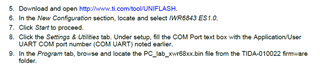
I am working on the People counting and tracking using mmWave radar sensor with sub-1 GHz reference design- TIDA 010022. Here I was successful in flashing the sensor and the collector nodes with the help of TI forum thread:

https://e2e.ti.com/support/wireless-connectivity/sub-1-ghz-group/sub-1-ghz/f/sub-1-ghz-forum/849626/launchxl-cc1352r1-tida-010022-design-people-counting-and-tracking-demo-using-iwr6843-and-sub-1-ghz-is-not-working-all-the-out-and-patch-files-are-outdated

Now, the sensor node is not transmitting any data read from the mmwave IWR6843ISK sensor. as there is no green light glowing on both collector and sensor(which indicates data transmission between the devices). Based on the example configuration details of sensor and collector configuration in the TI resource  explorer link:

https://dev.ti.com/tirex/explore/node?node=AFU6dryAU8NukjdRPy4T4Q__pTTHBmu__LATEST

Where in step 11, if the switch on collector is pressed then a  LED light on the sensor toggles. This step is completed successfully. This shows that the two devices are communicating and only data is not being transferred. Please help me resolve this issue to establish communication with the mmwave sensor.

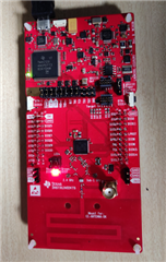
Below is the image of the boards after connecting the MMWAVEICBOOST, IWR6843ISK and sensor node.

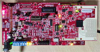
Below is the image of the collector node after the sensor node has joined the network.

Regards,

Vandana

  • Hello Vandana,

    Can you please confirm whether you made the modifications from the above linked post and how you know those binaries are working? It is not clear if you only flashed the devices or are able to run them?

    Also, can you please confirm whether you have been through the out of box demo for the IWR6843ISK and confirmed that the HW and SW connections to the radar devices are functioning?

    Thanks,

    Jackson

  • Hi Jackson,

    I have done all the modifications from the linked post that is flashing the collector and sensor nodes with the example code from SimpleLink SDK v3.30.00.03 and applied the patches provided by the post mentioned above.

    I have flashed the IWR6843ISK and MMWAVEICBOOST boards with the binary file provided in the TIDA-010022 firmware folder and it has been completed successfully. 

    In the instructions provided in the reference design document above they are asking to locate IWR6843 ES1.0. But when I try to flash the IWR6843ISK device. I don't get any such devices in the option. Could this be the issue?

    I have not done the out of the box demo for IWR6843ISK as there were hardware modifications to be done on the MMWAVEICBOOST Board .

    Is it possible to run the out of the box demo even after making these changes?

    Regards,

    Vandana

  • Hello,

    Yes it looks like it should still be fine to run the OOB demo. You will just need to set the switch settings back to default. These settings will be in the schematic for the ICBoost. Please make sure the OOB demo runs before setting up the wireless transfer. 

    Also, have you confirmed the sensor and collector lab runs without the input from the mmWave sensor? Have you tried sending dummy info over to make sure the connection is complete?

    Regards,

    Jackson

  • Hi,

    I will run the OOB demo to test the working of IWR6843ISK and MMwaveic BOOST. 

    Another thread on TI forum where they were discussing the connectivity issue between sensor and collector node.

    Post link:

    e2e.ti.com/.../rtos-launchxl-cc1352r1-the-cc1352r1-sensor-node-does-not-send-commands-to-the-iwr6843isk

    They are suggesting that sensor node connected to the PC through Teraterm should display a message 'dfeDataOutputMode 1' on the screen  that means the cc1352 is sending out commands.

    In my case this is happening. Could you please give me some information regarding how to send dummy info to check the connectivity so that I can confirm the connection between the two devices?

    Regards,

    Vandana

  • Hi, I ran the Out of the box demo and I was successful in visualizing the output on demo visualizer. I also found that the device I have is IWR6843ISK ES2.0 Antenna Module. But in the documentation they are suggesting to select to locate IWR6843 ES1.0.Could this be the reason for the binary file to not execute properly?

  • Yes, that would cause the program to not run correctly. Unfortunately the ES1 devices are not available and there is no easy to swap replacement binary. There are 2 main options for fixing this. 

    1. Take the OOB demo source code from the TI resource explorer for the mmWave, and modify it to use 2D pointcloud and tracking outputs. If you flash this, it looks like it should work with the stock sub1 binaries (or the recently modded ones for upgraded sub1 HW)

    2. Take the standard OOB demo, add the 3D tracking output, then modify the stock sensor and collector lab for the sub1 device to send the configuration and accept data over the UART lines.

    For checking the connection of the sub1 devices, I suggest you post a new question for that device, as it will be the easiest way to route it to the sub1 team.

    Best Regards,

    Jackson

  • As I am new to working with MMwave sensor 6843 and mmwave eic boost. I would like to know more about the OOB demo source code that you are referring to as there are different type of out of box demos given in the mmwave_industrial_toolbox_4_8_0.Could you please provide a link to that demo .

    Best Regards,

    Vandana 

  • Hello,

    Yes, sorry, the link is below. If you have downloaded the toolbox, you can find the source code at the below path.

    https://dev.ti.com/tirex/explore/node?node=AM1kRI3l5vvDUDVn-RHrxQ__VLyFKFf__LATEST

    C:\ti\mmwave_industrial_toolbox_4_8_0\labs\out_of_box_demo\68xx_mmwave_sdk_dsp

    While there are several different 'versions' of the OOB demo, the data processing path should mostly be the same, the differences may be at the application level. The standard OOB demo is what I have linked above for the IWR6843ISK EVM.

    Regards,

    Jackson

  • Hi, 

    Thank you for providing the link to the mmwave sdk. When I read the OOB demo documentation they are saying the output can be saved in .dat format in mmwave demo visualizer or through DCA1000. I also found another example 3D People Counting where the output is transmitted through UART in the following format.

    This is similar to the output from TIDA-010022. which is then transmitted through wireless transmission. Which one do you suggest that I should go on with?

    Regards,

    Vandana

  • Hello,

    I suggest using the mmWaveDemo Visualizer, as it will save the UART data. If you use the DCA, it will output raw ADC data which still needs to be processed. 

    All the labs use a similar UART output structure. For the OOB demo, make sure you see the following document with the OOB demo structure.

    C:\ti\mmwave_industrial_toolbox_4_8_0\labs\out_of_box_demo\common\docs\understanding_oob_uart_data.html

    Regards,

    Jackson

  • Hi,

    If I use the OOB demo, then I need to modify the code so as to get the UART output  data, which should be transmitted through the sensor node to the collector node in wireless and then data needs to be visualized through tera term. Is this how I need to proceed with the programming?

  • Yes that sounds like a good approach. You will just need to modify the sensor and collector node to match the expected data format that you use for the UART output.

  • Thanks a lot. I will start working on developing the application.