This thread has been locked.

If you have a related question, please click the "Ask a related question" button in the top right corner. The newly created question will be automatically linked to this question.

LDC1612EVM: GUI shows always 3 MHz Sensor frequency

Part Number: LDC1612EVM
Other Parts Discussed in Thread: LDC1612

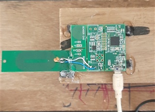
I am using LDC1612EVM with a PCB coil designed using spread sheet LDC_Tools-ext50.xlsx.

A Racetrack coil of 40x20 mm with 0.2 mm track spacing and 0.4 mm track width is designed using LDC_Tools-ext50.xlsx.

Coil value is calculated as 12.974 uH. Spread sheet calculates 4.138 MHz with 110 pF capacitor. Q is calculated 85. RP 28.8 K.

I have disconnected ch1 coil on EVM board.  When I connect above customized  coil to LDC1612EVM Ch1, it shows frequency Value 3.03 MHz and coil value 25.0 uH. Any capacitor value I connect on EVM ch1 and set same value on GUI, it shows fix 3.03 MHz frequency always and changes only L value. I expect GUI to measure and show 4.138 MHz frequency and about 12.97 uH inductor value for Ch1.

Ch0 coil on EVM is not disconnected. GUI is configured for Ch1 Repeat Measurements.

Application is to detect a metal object of  @ 3 mm distance. Spread sheet shows frequency shift of 65 KHz, but practically I detect only 1 to 3 KHz frequency shift.

Request tLDC Spread Sheet & GUI Screen Shots _1.pdfour technical help to resolve the issue. Screen snaps of GUI and spread sheets are attached herewith.

  • Vijay,

    Is it possible to verify the sensor signal level and frequency for CH0 and CH1 with an oscilloscope?

    Regards,
    John

  • Hello John,

    Thanks for quick response. As suggested, I shall measure frequency on  INAx or INBx pin to GND OR on any one end of the coil to GND.

  • Hello John,

    Please find Oscilloscope Screen captures for the LDC1612EVM. It is configured for repeat single ch-1 measurements, IDRIVE1 current 108 uA, code 13. Signal measured on one end of the coil is half sine wave. Identical signal is observed on second pin of the coil. Is it ok?. Signal frequency is 3.125 MHz, Amplitude for above IDRIVE setting is 1.68 V with target away from the coil, 1.64 V when target is 2 mm away from the coil. GUI displays same frequency 3.124569 MHz., L value 25.68 uH.  Expected frequency is 4.14 MHz with 100 pF capacitor in the tank circuit, L value 12.974 uH. Tweaking with IDRIVE current and RCOUNT value for 15 bit resolution, I now see frequency shift of approx. 20 KHz, with and without target. Expected freq. shift calculated with LDC spread sheet is 65 KHz.  Even if I connect and set 330 pF capacitor value, frequency remains same but L value changes to 7.86 uH. Waiting for your guidance to improve it to calculated value, and reason for lower frequency then expected.Oscilloscope Screen.pdf

  • Vijay,

    Thank you for the additional data.
    Some things to try:

    1. What self-resonant frequency does the spreadsheet tool report for your coild design?
    2. When you change the capacitor on the EVM, are you updating the Parallel Capacitance value on the GUI Configuration page?
    3. When you change the capacitors, can you try confirming the frequencies reported by the GUI with the oscope?
    4. If you haven't done it already, can you try maxing out the value of RCOUNT (xFFFF)?
    5. Can you use a signal generator to help estimate the value of your sensor? 
      You can do this by using your sensor  in an LPF configuration with a 330 ohm resistor. Make sure the sensor is away from any metal. If the sensor is the intended inductance, the LPF roll-off with the 330 ohm resistor should have a -3dB corner at the same frequency calculated for resonance - 4.138MHz.

    Regards,
    John

  • Hello John,

    Please find response to your queries below.

    1. LDC spread sheet calculates SRF of coil 22.093 MHz. I had attached the LDC and GUI Screen shoots.pdf in  this thread above.
    2. Every time I change capacitor value on the EVM, I also change the capacitor value  on GUI.
    3. Frequency is confirmed on the oscilloscope. It is same as on GUI. No change.
    4. I just now tried Reference count 0xFFFF (65535), but frequency is  same 3.1245 MHz.  
    5. I will try to measure coil response in LPF configuration, or shall measure it on LCR meter. I will try if I can manage instruments.

    In the mean time, I will also wait for your valuable suggestions for further diagnostic testing .   

  • Vijay,

    I think the next step is to confirm the coil's inductance is as expected.
    The coil serves as the input, so if it is off, our troubleshooting efforts will be compromised from the beginning.

    It would be great if you could measure it with an LCR meter over a set of frequencies that  includes the intended resonant frequency and the coil's self-resonant frequency.
    Please be sure to consider any connections you are using between the coil and he EVM.
    These can add parasitics that can affect the measurements and troubleshooting.

    If you could include a photo of the EVM with your coil attached, that could be helpful.

    Regards,
    John

  • John I shall be back with Coil measurement results, coil-EVM photo. I need to manage instruments for the measurements.

  • Hello John,

    I am extremely sorry for the delay,  I could not manage Impedance analyzer which can measure over the desired freq band. But I could test the coil in LPF mode, with a signal generator and a oscilloscope. With 328 Ohm resistor in LPF , I observed half power freq 3.65 MHz. Back calculated L value as 14.3 uH. With the fix frequency 100 KHz Impedance and LCR meter of key Sight, it measures 16 uH. I seek your further advice.I have tested the coil with the LDC1612 EVM. Considering L value 14.3 uH, as measured in LPF configuration and with measured value of a 90 pF capacitor , expected frequency was 4.4 MHz. But Sensing Solution GUI measures it 19 uH, frequency 3.9 MHz.

    With this coil, detection sensitivity is very very less. Freq. shift is only 600-800 Hz. Target is to get about 10 KHz frequency shift. My main application is to detect an object of 10mm length, 0.5 mm thickness (a small staple pin)anywhere in the span of 50 inches, placing multiple coils over the span. To cover the span with minimum possible number of coils, I have chosen bit larger coil size of 40x20 mm racetrack. I have multiple doubts in mind like Is my choice of coil size correct ? is the selection of LDC1612 is correct? Whether higher Q coil is better for the application or lower Q coil is better? you may kindly suggest any other, more sensitive LDC device for this application or proper coil type and size.

    With this I have attached photograph of the coil and EVM.

  • Vijay,

    Until now I did not understand the small size of the target you want to detect. My apologies. I should have asked. 
    In general, larger targets are easier to detect than smaller targets, and the smaller a target is relative to the size of the coil, the harder it is to detect.
    This covered in more detail in the blog post Inductive sensing: target size matters.

    You mentioned your air gap is 3mm. 
    I'm not sure it would help, but is it possible to reduce it to something less, or make the object you want to detect larger?

    Another option might be to use a stretched coil as described in section 3.1 of LDC1612/LDC1614 Linear Position Sensing for position detection.
    The app note describes a position-detection application that uses a target that is smaller than the coil size.
    We can't say for sure that this option would work, and we don't have a tool to analyze the inductance of a coil like this, but our LDCCOILEVM does have coils like this to experiment with. 

    Another option might be to use a larger number of smaller coils to reduce the size differences between the target and coil, but there can be practical limits to this as well. There is a blog post that outlines the use of a small coil. 

    Again, apologies for not recognizing the use of a small target. 
    I hope some of the options above will help.
    Please let me know if you have any questions.

    Regards,
    John

  • Thanks John,

    As for the object size I mentioned in my previous post, 10 x 0.5 mm is the worst case. I have tested LDC with a best use case, a 3mm round, 1 mm thick Al. object. I measured a good frequency shift of about 22 KHz at 2 mm distance, with the same Race Track coil of 40x20 size.

    As for the air gap, it can be as small as 1 mm. 3 mm air gap is the worst case condition.

    I shall go through the references you have mentioned. Particularly the blog describing the use of a small 2 mm coil in series with the sensor coil is an interesting experiment I would like to conduct.

    For further experiment, it may take few days to come to a conclusion. I herewith request to keep this case open so that I will have continuity for the discussion and advise from you.

    Regards and Thanks