This thread has been locked.

If you have a related question, please click the "Ask a related question" button in the top right corner. The newly created question will be automatically linked to this question.

AWR1843AOPEVM: AWR1843: How to frame sync among some AWR1843s

Part Number: AWR1843AOPEVM
Other Parts Discussed in Thread: AWR1843AOP, AWR1843

Hi,

I'm trying to make two AWR1843s work in a synchronous mode.But i have some problems.I would like to know all the information to the way to frame sync among some AWR1843s (it is different from cascade).

I just do as follows:

  1. I modify code in function "void MmwDemo_mssInitTask(UArg arg0, UArg arg1)" of mss_main.c as this:

Pinmux_Set_OverrideCtrl(SOC_XWR18XX_PINP4_PADBB, PINMUX_OUTEN_RETAIN_HW_CTRL, PINMUX_INPEN_RETAIN_HW_CTRL);
Pinmux_Set_FuncSel(SOC_XWR18XX_PINP4_PADBB, SOC_XWR18XX_PINP4_PADBB_SYNC_OUT); // set PADBA as SYNC_OUT mode

I also try this way:

Pinmux_Set_OverrideCtrl(SOC_XWR18XX_PING13_PADBC, PINMUX_OUTEN_RETAIN_HW_CTRL, PINMUX_INPEN_RETAIN_HW_CTRL);
Pinmux_Set_FuncSel(SOC_XWR18XX_PING13_PADBC, SOC_XWR18XX_PING13_PADBC_SYNC_OUT); // set PADBC as SYNC_OUT mode

2.rebuild the project and flash it to my board.

3.config the board by uart. The config cmd is

sensorStop
flushCfg
dfeDataOutputMode 1
channelCfg 15 1 0
adcCfg 2 1
adcbufCfg -1 0 0 1 1
profileCfg 0 77 10 5 40 0 0 99.987 3 256 8000 0 0 36
chirpCfg 0 0 0 0 0 0 0 1
frameCfg 0 0 2 0 25 1 0
lowPower 0 1
guiMonitor 1 1 0 0
cfarCfg 1 4 1 1 2 8 2 350 30 2 0 5 50 0.5
dbscanCfg 4 4 13 20 3 256
sensorStart

 4.When the board works in single board mode, it can work normally. At this time frameCfg is as follows:

frameCfg 0 0 2 0 25 1 0

But the synchronization signal cannot be measured on the corresponding pin.

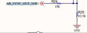
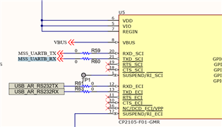
5.The pin connection relationship is shown in the figure below:

6.The oscilloscope I use is Tektronix TBS1102C, the sampling frequency is set to 1GHz, the bandwidth is full bandwidth, and the trigger method is rising edge trigger.

Any additional info that would be helpful would be greatly appreciated as well.  Thanks for all your help!

  • Hello,

    It can be hard to measure the sync out signal unless you have a high bandwidth scope. Please see below thread for reference. You may not be able to see it on the 100MHz scope.

    https://e2e.ti.com/support/sensors-group/sensors/f/sensors-forum/1004468/awr1843-source-code-for-awr1843-out-of-box-demo-for-use-in-data-visualizer-sync-out-firmware-adaptation

    Can you clarify which pin you are attempting to measure? I am assuming the SYNC_OUT pin, but the second screen shot of the UART to USB converter is confusing as I am not sure what you are trying to show in that image.

    Did you try setting the second device for hardware triggered mode and connecting the two boards together to see if it worked?

    Regards,

    Adrian

  • Hi,

    1.

    I try two ways:

    a).It was the first method I tried. The pinmap is:

    U12→MSS_UARTB_RX→TXD_SCI.

    Where U12 is the pin of AWR1843AOP, TXD_SCI is the pin which i'm tring to measure the sync out signal. TXD_SCI is connected to the USB converter, because in another application, the u12 pin is used as a serial port output pin. I'm not sure if this way of hardware connection will cause sync signal anomaly when I use U12 as syncout pin.  

    The corresponding code is:

    Pinmux_Set_OverrideCtrl(SOC_XWR18XX_PINP4_PADBB, PINMUX_OUTEN_RETAIN_HW_CTRL, PINMUX_INPEN_RETAIN_HW_CTRL);
    Pinmux_Set_FuncSel(SOC_XWR18XX_PINP4_PADBB, SOC_XWR18XX_PINP4_PADBB_SYNC_OUT); // set PADBA as SYNC_OUT mode 

    b).It was the second method I tried. The pinmap is:

    M3→ AR_SYNC_OUT_SOP1

    Where M3 is the pin of AWR1843AOP, AR_SYNC_OUT_SOP1 is the pin which i'm tring to measure the sync out signal. AR_SYNC_OUT_SOP1 is connected to ground through two resistors R24(10k) and R25(82.5k). There was originally a pull-up circuit on this line, which has been disconnected by me.

    The corresponding code is:

    Pinmux_Set_OverrideCtrl(SOC_XWR18XX_PING13_PADBC, PINMUX_OUTEN_RETAIN_HW_CTRL, PINMUX_INPEN_RETAIN_HW_CTRL);
    Pinmux_Set_FuncSel(SOC_XWR18XX_PING13_PADBC, SOC_XWR18XX_PING13_PADBC_SYNC_OUT); // set PADBC as SYNC_OUT mode

    2.

    Yes, I've tried connecting two identical boards together, but only the master board works, the slave board doesn't work. My setup is as follows:
    Hardware connection: The Syncout pin of the master board is connected to the Syncin pin of the slave board.The GND pin of the master board is connected to the GND pin of the slave board.
    Software configuration: The configurations of the two boards are the same, except that the trigger mode is different, and the master board is configured as soft trigger mode, that is: frameCfg 0 0 2 0 25 1 0. The slave board is configured as hard trigger mode, that is: frameCfg 0 0 2 0 25 2 0


    I also tried to set the frame period of the slave board to be greater than that of the master board, such as setting the frame period of the slave board to 26ms, but the slave board still does not work.

  • Hi,

    Do you have any solutions or suggestions for my problem? Looking forward to your reply.

    Regards,

    jianwen tong

  • Dear Jianwen - 

    Sorry for the delay - Adrian has been on vacation all this week - have you tried swapping roles between the two boards you are using, to ensure the slave board is OK? 

  • Hello,

    Looking at your code, I think this may be a pinmux issue. Please refer to the below thread for correct pinmux header file for 1843AoP since pinmapping is different from AWR1843. 

    https://e2e.ti.com/support/sensors-group/sensors/f/sensors-forum/1024687/faq-awr6843aop-mmwave-sdk-pinmux-awr1843aop-and-awr6843aop

    Regards,

    Adrian