Other Parts Discussed in Thread: AWR1843AOP, AWR1843
Hi,
I'm trying to make two AWR1843s work in a synchronous mode.But i have some problems.I would like to know all the information to the way to frame sync among some AWR1843s (it is different from cascade).
I just do as follows:
- I modify code in function "void MmwDemo_mssInitTask(UArg arg0, UArg arg1)" of mss_main.c as this:
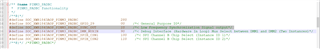
Pinmux_Set_OverrideCtrl(SOC_XWR18XX_PINP4_PADBB, PINMUX_OUTEN_RETAIN_HW_CTRL, PINMUX_INPEN_RETAIN_HW_CTRL);
Pinmux_Set_FuncSel(SOC_XWR18XX_PINP4_PADBB, SOC_XWR18XX_PINP4_PADBB_SYNC_OUT); // set PADBA as SYNC_OUT mode
I also try this way:
Pinmux_Set_OverrideCtrl(SOC_XWR18XX_PING13_PADBC, PINMUX_OUTEN_RETAIN_HW_CTRL, PINMUX_INPEN_RETAIN_HW_CTRL);
Pinmux_Set_FuncSel(SOC_XWR18XX_PING13_PADBC, SOC_XWR18XX_PING13_PADBC_SYNC_OUT); // set PADBC as SYNC_OUT mode
2.rebuild the project and flash it to my board.
3.config the board by uart. The config cmd is
sensorStop
flushCfg
dfeDataOutputMode 1
channelCfg 15 1 0
adcCfg 2 1
adcbufCfg -1 0 0 1 1
profileCfg 0 77 10 5 40 0 0 99.987 3 256 8000 0 0 36
chirpCfg 0 0 0 0 0 0 0 1
frameCfg 0 0 2 0 25 1 0
lowPower 0 1
guiMonitor 1 1 0 0
cfarCfg 1 4 1 1 2 8 2 350 30 2 0 5 50 0.5
dbscanCfg 4 4 13 20 3 256
sensorStart
4.When the board works in single board mode, it can work normally. At this time frameCfg is as follows:
frameCfg 0 0 2 0 25 1 0
But the synchronization signal cannot be measured on the corresponding pin.
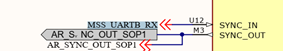
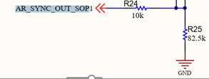
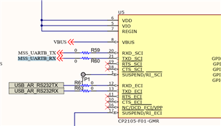
5.The pin connection relationship is shown in the figure below:
6.The oscilloscope I use is Tektronix TBS1102C, the sampling frequency is set to 1GHz, the bandwidth is full bandwidth, and the trigger method is rising edge trigger.
Any additional info that would be helpful would be greatly appreciated as well. Thanks for all your help!