Tool/software:
Hi all,
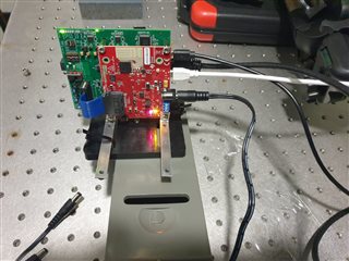
I am facing some weird errors while running the TI radar kit (DCA1000EVM and AWR2243B).
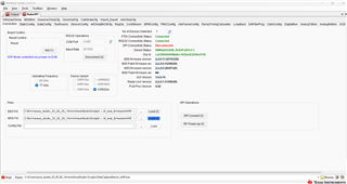
Everytime I try to use the mmwave studio in the connection tab I press RS232 Connect switch and I upload the BSS and MSS firmwares, and then when I press the SPI connect switch it shows some errors. I have tried changing the Power Supply and also tried restarting the Radar, but it does not work.
The SPI connectivity status remains always disconnected.
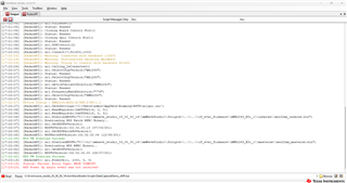
The error is :
[17:22:27] [RadarAPI]: ar1.SaveSettings('C:\Users\admin\AppData\Roaming\RSTD\ar1gui.ini')
[17:22:36] [RadarAPI]: ar1.ReadRegister(0xffffe214, 0, 31)
[17:22:36] [RadarAPI]: ar1.ReadRegister(0xffffe218, 0, 31)
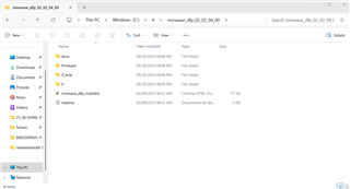
[17:22:36] [RadarAPI]: ar1.DownloadBSSFw("C:\\ti\\mmwave_studio_03_00_00_14\\mmWaveStudio\\Scripts\\..\\..\\rf_eval_firmware\\AWR2243_ES1_1\\radarss\\xwr22xx_radarss.bin")
[17:22:37] [RadarAPI]: Downloading BSS Patch RPRC Binary..
[17:22:37] [RadarAPI]: ar1.GetBSSFwVersion()
[17:22:37] [RadarAPI]: BSSFwVersion:(02.02.00.13 (07/03/20))
[17:22:38] [RadarAPI]: ar1.GetBSSPatchFwVersion()
[17:22:38] [RadarAPI]: BSSPatchFwVersion:(02.02.02.06 (12/08/20))
[17:22:38] BSS FW Download Success
[17:22:38] [RadarAPI]: ar1.DownloadMSSFw("C:\\ti\\mmwave_studio_03_00_00_14\\mmWaveStudio\\Scripts\\..\\..\\rf_eval_firmware\\AWR2243_ES1_1\\masterss\\xwr22xx_masterss.bin")
[17:22:39] [RadarAPI]: Downloading MSS RPRC Binary..
[17:22:42] [RadarAPI]: ar1.GetMSSFwVersion()
[17:22:42] [RadarAPI]: MSSFwVersion:(02.02.02.00 (29/07/20))
[17:22:42] MSS FW Download Success
[17:23:18] [RadarAPI]: ar1.PowerOn(1, 1000, 0, 0)
[17:23:18] Status: Failed, Error Type: RESP TIMEOUT
[17:23:23] MSS Power Up async event was not received!
Please help me so that I can use it.
Thanks and regards,
Niladri
Hi,
Were you able to connect to SPI previously and suddenly MSS does not power up?
Could you try to download and load the BSS/MSS patches from DFP_2_2_4_0 MMWAVE-DFP-2G Firmware | TI.com? If you are still having issues, please share the set-up image here.
Regards,
Aydin
Hi Aydin,
Thanks for your prompt reply!!!
Yes I was able to perform measurements with this Radar Kit for the past 2months. Suddenly it happened yesterday. Also at 1st yesterday the adcdata.bin was not getting created at the postproc folder and so I restarted the radar kit and this happened.
Could you try to download and load the BSS/MSS patches from DFP_2_2_4_0 MMWAVE-DFP-2G Firmware | TI.com?
Could you please tell me how to load the patches from DFP folder?
Thanks and regards,
Niladri
Hi,
I have tried loading the firmwares from the DFP folders (both of them - firmware & RF_eval), but I am facing the same problem...
[17:23:18] Status: Failed, Error Type: RESP TIMEOUT
[17:23:23] MSS Power Up async event was not received!
I am attaching the screenshot of setup here:
Thanks and regards,
Niladri
Hi Aydin,
Also there is one thing I need to ask you regarding the chirp-calculation.
Could you please tell me how do I set a chirp of 1ms length and bandwidth of 6 Ghz in the mmwave studio? Could you please help me?
Thanks and regards,
Niladri
Hi Niladri,
There is a switch on the EVM board, S1, which I can't tell the direction from your image, but could you make sure that SPI is selected?
Now to your second question, the maximum chirp bandwidth you could do is with VCO2 and that will be 5GHz. Please refer to "AWR_PROFILE_CONF_SB" API in the mmWave Interface Control Document (ICD), so you will need to design your chirp within this bandwidth.
Please refer to the calculator within the mmWave_studio under (RampTimingCalculator) as there are other dependencies (There are also example calculations in the ICD document section12.4.1 Note on idle time for clearing the watchdog (WDT) explaining the chirp timing calculations).
Regards,
Aydin
Hi Aydin,
Thanks for your message. From the troubleshooting that you told me I am now able to fix the TI Radar kit and this works now.
Thanks very much.
For the 2nd question, Can you please give me an explanation about how to design the chirp with the necessary criteria that I mentioned in the previous message? I was trying to design the chirp in the SensorConfig section of the mmwavestudio, but I cannot get my desired criteria.
I want the idle chirp time = 0 and 1 chirp of 1 ms length with the bandwith of around 5-6 GHz.
So I changed the freq. slop to 6 MHz/us, idle time = 0, ramp end time = 1000us, ADC samples = 4096 and when I set it I am getting error.
Could you please help me?
Will you suggest something that will come closer to my desired criteria?
Thanks and regards,
Niladri
Hi Niladri,
Glad to hear, SPI connects and you're able to capture.
The Max bandwidth you can achieve as also noted in the ICD is 5GHz with VCO2 and for a 5GHz BW over 1mS, the required slope is about 5000MHz/us which is violating the maximum allowed slope. The idle time can't be zero you need to define some idle time. My suggestion would be reducing your chirp duration and adjusting the slope to be within the supported limits and allowing a sufficient Idle time. I would recommend the following application note to go over Programming Chirp Parameters in TI Radar Devices (Rev. A) in which we have every detail of designing a chirp. In addition, you could use the calculator within the studio. For the specific API's please refer to the Interface Control Document. if any software dev specific questions arise, please open a new thread and the software team would be able to assist further.
Regards,
Aydin
Hi Aydin,
Wish you a good afternoon.
I have a few queries related to AWR2243B. They are:
1. Can we increase the intermediate freq signal (IF signal)? Or is it fixed for a particular radar kit? If yes then how?
2. Will you also please tell me about the combination of highest possible bandwidth and the smallest chirp that I can configure with this Radar kit? I know the highest possible bandwidth is 4 GHz. Please let me know about the smallest possible chirp length.
3. Please let me know the highest possible Sampling freq. that we can configure for our radar kit.
Looking forward to your reply.
Thanks and regards,
Niladri
Hi Niladri,
1. Can we increase the intermediate freq signal (IF signal)? Or is it fixed for a particular radar kit? If yes then how? There is a MAX IF frequency that every device supports, and the IF frequency falls within that limit depending on the object being close or far. In this case of AWR2243, Max IF frequency is 20MHz.
2. Will you also please tell me about the combination of highest possible bandwidth and the smallest chirp that I can configure with this Radar kit? I know the highest possible bandwidth is 4 GHz. Please let me know about the smallest possible chirp length.
The minimum value is 48.279kHz/uS and maximum value is 266MHz/uS. Please refer to the ICD section 5.5.
3. Please let me know the highest possible Sampling freq. that we can configure for our radar kit.
The highest sample rate is 45Msps in AWR2243.
Regards,
Aydin
Hi Aydin,
Thank you so much for these information.
As per the technical notes I can see that the minimum chirp time(chirp to chirp time) for AWR2243BOOST is 13 us.
Is this Idle time + ramp end time = 3+10 us?
Also please let me know the max chirp time?
There is one more thing to ask from you that is Periodicity. As far I can understand from the technical notes is it = no. of chirps * chirp time i.e. (128 * 13) us = 1.664 ms ?
Please let me know about these.
Thanks and regards,
Niladri
Hi Niladri,
As per the technical notes I can see that the minimum chirp time(chirp to chirp time) for AWR2243BOOST is 13 us.
Is this Idle time + ramp end time = 3+10 us?
Minimum chirp to chirp should be >=13uS. The minimum Idle time is 2.5uS should be maintained.
Also please let me know the max chirp time? It depends on the Bandwidth. Total chirp time = Active chirp time + Idle time & Active chirp time = BW/Chirp slope
You could use the above slopes I provided based on the ICD for AWR2243 and calculate the total chirp time.
There is one more thing to ask from you that is Periodicity. As far I can understand from the technical notes is it = no. of chirps * chirp time i.e. (128 * 13) us = 1.664 ms ?
You can calculate the Frame period by using the following:
Frame period = ((idleTime + rampEndTime) x numberChirps x numberChirpLoops ) + Inter-frame time
I would recommend using the mmWave sensing estimator to aid with the calculations for your specific application.
https://www.ti.com/mmWaveSensingEstimator
Here is another application note we have on the chirp programming Programming Chirp Parameters in TI Radar Devices (Rev. A)
Regards,
Aydin