This thread has been locked.

If you have a related question, please click the "Ask a related question" button in the top right corner. The newly created question will be automatically linked to this question.

TDC1000: Two echo pulses only generate one stop pulse

Part Number: TDC1000

Hi there!

I'm investigating the possibilities of TDC1000 with 40kHz transducers in air.

Strangely, only one stop pulse for every two echo pulses seems to be generated.

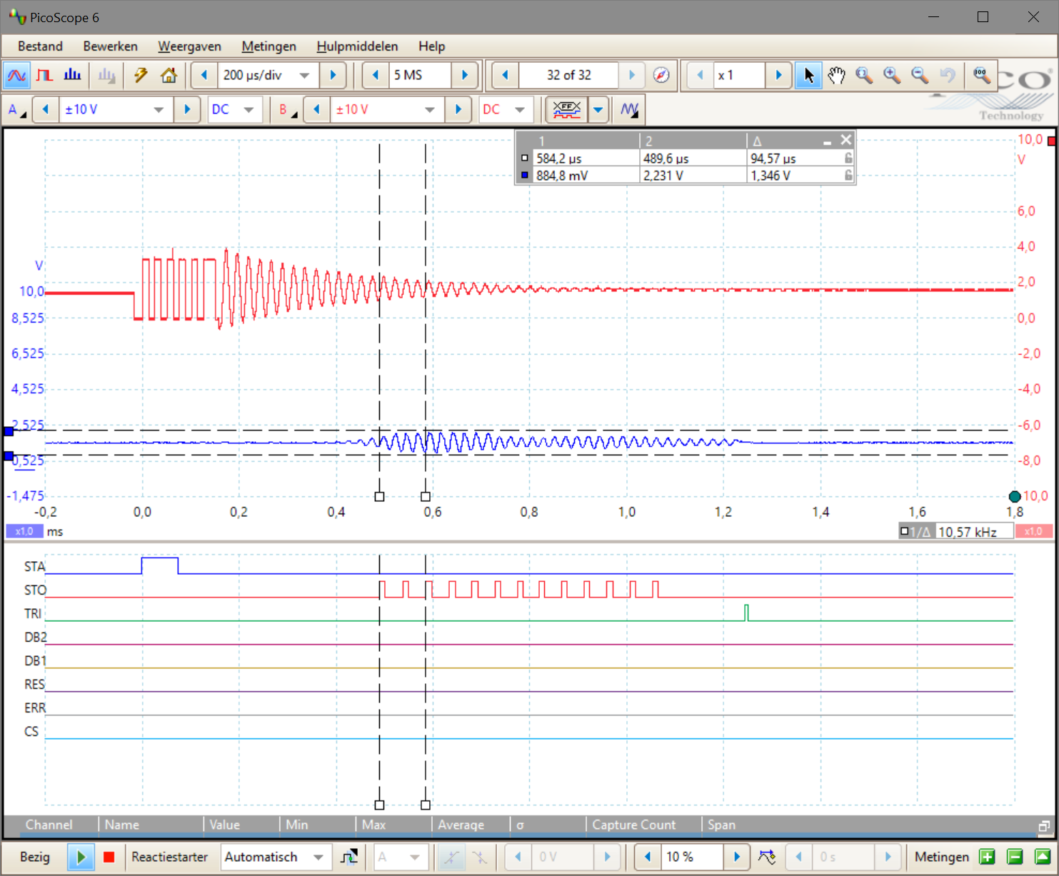
Following scope picture illustrates the problem:

Between the two vertical dotted lines, 4 echo pulses can be seen (blue) while only 2 stop pulses are generated (red below, marked with 'STO').

I also wonder what determines the width of the stop pulses, as the datasheet does not seem to mention it.

For completeness I included the complete register dump of the TDC1000 (CLKIN = 80kHz, not using the EVM software):

T0:				12.50 us
T1:				25.00 us
TX_CLOCK:			40000.00 Hz
CONFIG_0
	RAW:			0x6
	TX_FREQ_DIV:		2
	NUM_TX:			6
CONFIG_1
	RAW:			0x40
	NUM_AVG:		1
	NUM_RX:			0
CONFIG_2
	RAW:			0x22
	VCOM_SEL:		INT
	MEAS_MODE:		TOF
	DAMPING:		ON
	CH_SWP:			OFF
	EXT_CHSEL:		OFF
	CH_SEL:			1
	TOF_MEAS_MODE:		2
CONFIG_3
	RAW:			0x4
	TEMP_MODE:		REF, RTD1, RTD2
	TEMP_RTD_SEL:		PT1000
	TEMP_CLK_DIV:		8
	BLANKING:		OFF
	ECHO_QUAL_THLD:		-220 mV
CONFIG_4
	RAW:			0x1F
	RECEIVE_MODE:		SINGLE ECHO
	TRIG_EDGE_POLARITY:	RISING
	TX_PH_SHIFT_POS:	31
TOF_1
	RAW:			0xE4
	PGA_GAIN:		21 dB
	PGA_CTRL:		ON
	LNA_CTRL:		ON
	LNA_FB:			RESISTIVE
	TIMING_REG[9:8]:	0
TOF_0
	RAW:			0x0
	TIMING_REG[9:0]:	0
ERROR_FLAGS
	RAW:			0x0
	ERR_SIG_WEAK:		0
	ERR_NO_SIG:		0
	ERR_SIG_HIGH:		0
TIMEOUT
	RAW:			0x4C
	FORCE_SHORT_TOF:	ON
	SHORT_TOF_BLANK_PERIOD:	16 x T0 -> 200.00 us
	ECHO_TIMEOUT:		OFF
	TOF_TIMEOUT_CTRL:	128 x T0 -> 1600.00 us
CLOCK_RATE
	RAW:			0x0
	CLOCKIN_DIV:		1
	AUTOZERO_PERIOD:	64 x T0 -> 800.00 us
TOF Control:			Short TOF
Common-mode:			1600.00 us
Autozero:			800.00 us
Transmit:			150.00 us
Mask/Blank:			200.00 us
Echo listen:			1600.00 us
End:				25.00 us

Thanks in advance!

  • Hi Ivo,

    This behavior is new to me. I will have to do some tests to take a look at this. I should be able to get back to you by the end of the week. In the meantime, can you test this with a higher frequency transducer?

    Regards,
  • Hi Scott,

    Unfortunately 40kHz transducers are the only types I have available.

    It's not blocking me right now, so I'll just wait for your tests.

    Thanks!

  • Hi Scott,

    Any updates on the issue?

    What also bothers me is the duration of the start pulse (blue pulse marked 'STA'). It is around 75 us wide, while, according to the datasheet, PWstart (chapter 6.7) should typically be only 3 us wide.

    Thanks,

    Ivo

  • Hi Ivo,

    Apologies for the delay. I need to look into this more.

    Keep in mind the test conditions for the PWstart as shown in the table. Those numbers are for a 1Mhz transmit frequency. For transmit pulse numbers less than 3, the start pulse width is equal to the period of the transmission multiplied by the number of pulses, and for transmit pulses greater than 3 it is always equal to the period of the pulses times 3.

    In your case the period of the pulses is 25us, and with more than 3 pulses, the start pulse width should be 75us. Please see note B below:

  • Hi Ivo,

    What is the source of your clock? Can it easily be changed? My first thought would be to increase the frequency of the clock even if the transmit frequency must stay the same.

    To answer your question about what drives the stop signal low again, it is included in the datasheet under the zero-cross detect comparator section, but it is not clearly described. The zero-cross detector output is what is ultimately passed through as the stop signal when it has been qualified by the threshold detection. The zero-cross detect signal will go low (and the corresponding stop signal) as soon as the compin  signal goes below VCOM -- 10mv of hysteresis.

  • Hi Scott,

    I'm using a SI5351A clock generator, so I can test with any frequency.
    In fact I already did some tests multiplying the frequency (went up to a few MHz iirr) and chosing appropriate divider, but results were the same.
    I have some 200khz transducers on order, but lead times are rather long.
    Description of the width of the stop pulse is clear now, thanks for that!

    Regards,
    Ivo
  • Hi Scott,

    A few weeks have passed and I'm still awaiting your results for 40KHz transducers as the main issue is still unsolved. Are you still investigating my issue?

    The 200KHz transducers have arrived, but they appear to be DOA, so that doesn't help either...

    Ivo

  • Hi Ivo,

    So far I have been unable to replicate the issue. I am working on it more this week.

    Regards,
  • Hi Ivo,

    Apologies for the delay. I believe this may be related to a similar known behavior of the TDC1000 in multiple echo mode. In that case, the STOP signal will be generated 1 pulse too late on every echo signal after the first one. Until now I had only seen it appear in multiple echo mode, but it seems that if the period of the signal is large enough it can show up in single echo mode. Currently there is no workaround for this within the TDC1000, and for multiple echo mode the best option is to subtract that extra period from the total time measured. I will let you know if a solid workaround is developed.

    Regards,