This thread has been locked.
If you have a related question, please click the "Ask a related question" button in the top right corner. The newly created question will be automatically linked to this question.
Hi,
Our Customer using MMWCAS-RF/DSP-EVM .but The DSP EVM didn't boot .
We checked the status of it as below .
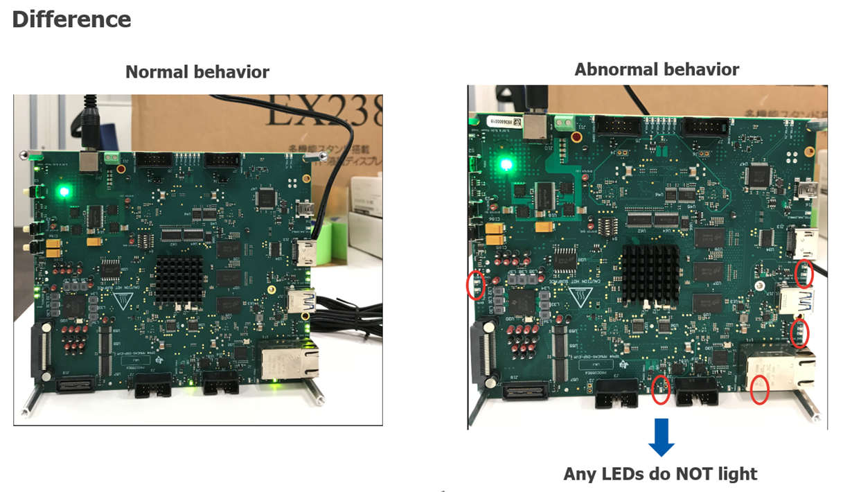
Left is normal EVM behavior ,Right is wrong EVM behavior
1)We checked using customer's RF board and our normal DSP board.
-->no issue ,it's booted .
2)Customer RF board and customers DSP board ,
--->it’s not booted ,no out put data on PC text console .
Hard ware setting is same 1) and 2)
Please give us your opinion.
Best Regards
Hi,
The DSP EVM boots up with an image flashed to an SD card. There is a debug UART (J16) to which the bootup logs are logged.
Please ensure that the same SD card is used in both cases.
Please also check if there is any difference in the messages being sent out on this UART in the two cases.
Best Regards,
Anand
Anand-san,
Thank you for reply.
We use same SD card,but the worng DSP board doesn't send out any message .
Best Regards
Akira
Hi Akira,
Can you please comment on the exact 12V power supply being used to power the MMWCAS-DSP-EVM and MMWCAS-RF-EVM assembly? I recommend at least a 12V, 5A supply.
Thank you,
-Randy
Hi Randy-san,
Yes ,we did it under recommended conditions.
Best Regards.
AKira
Hi Akira,
Based on the LED that are not lighting up, that looks like the primary 3.3V/5.0V switching regulator (U18) may not be functional or the secondary, TDA2 PMIC (U 20) is not functional.
A few more things to try:
I am switching this thread to the Automotive Processors team for further support.
Thank you,
-Randy
Of the times I have seen this behavior it has been power related.
Does the customer EVM never power up or does it do this behavior randomly?
A few things to check:
1)Check the barrel connector for the power supply. Sometimes there is a loose connection causing the EVM to not fully power up, thus it cannot boot.
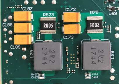
2)On the back side of the board between the 2 large power inductors, there are some small SMD components. Check to make sure they are properly soldered. In the past I have had to touch up the solder joints to fix this type of issue.
Thanks,
Alec
Randy-san,Alec-san,
Thank you for replies.We confirm about your requests.
* Can you please apply 12V power to the EVM and then momentarily depress the S1 switch? This switch controls an optional power monitor circuit which is used allow the push-button to power on the U18 regulator. If not disabled correctly, this switch will keep the U18 in reset mode, which would keep U18 regulator and U20 regulator both disabled.
=> I tried to push S1 when 12V is supplied. However, I could not confirm any improvement.
* Could you measure the input current you are getting for the powered on device? Comparing the good and bad boards.
=> I did not have good board in my side. so I checked only input currect of bad board by using current probe.
Current is arround 60mA(Too low current).
1)Check the barrel connector for the power supply. Sometimes there is a loose connection causing the EVM to not fully power up, thus it cannot boot.
=> I confirmed that barrel connctor connect properly. I also confirmed that 12V voltage is suppied at jumper pin.
2)On the back side of the board between the 2 large power inductors, there are some small SMD components. Check to make sure they are properly soldered. In the past I have had to touch up the solder joints to fix this type of issue.
=> I confirmed large inductor and small SMD components is implemented as shown below.
I performed deep dive to confirm root cause.
Then, I noticed about below.
* 5V Output from TPS43351 is not output correctly (Observed arround only 1.3V).
(3.3V is output correctly.)
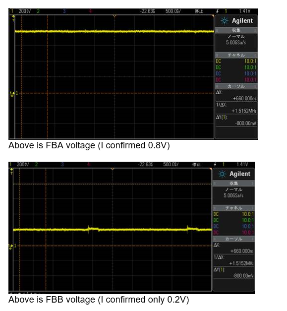
I confirmed that FB pin. Then I believe that 0.8V should be observed if device work correctly.
However, in case of 5V, I confirmed only 0.2V.
So, it seems feedback loop does not work.
We think this board is initial failure. we request a replacement for a good one.