This thread has been locked.

If you have a related question, please click the "Ask a related question" button in the top right corner. The newly created question will be automatically linked to this question.

Capacitive touch suggestion

Other Parts Discussed in Thread: MSP430FR2532, MSP430FR2632

Hi, 

we are using capacitive touch sensor for our application. 

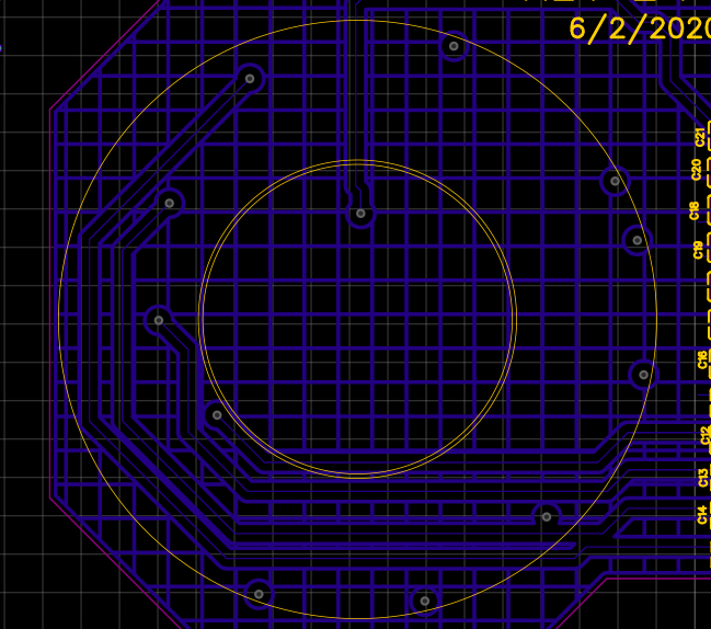
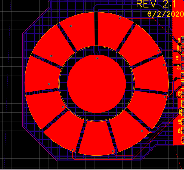
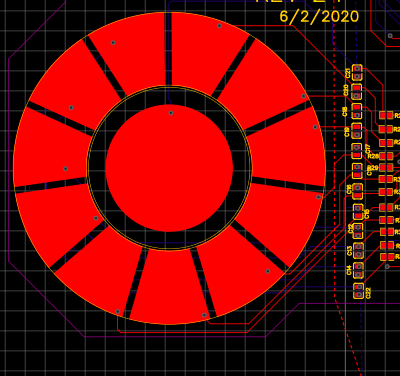
The design is attached below

The capacitive touch sensor  has a 2.5 mm thick ABS sheet above the touch sensor.

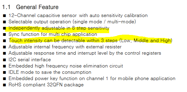
Could you please suggest any capacitive touch sensor IC's ?

The dimensions of the design are

  1. the diameter of inner circle ( button) is 16mm
  2. The spacing between capacitive pads are 0.9 mm
  3. length of the pads 9.27mm
  4. area of each pad  is 70.84 mm2

Thank-you

Warm Regards

Harini Krishna


  • Hello Harini,

    The design will require an MCU with at least 12 self capacitive pins.

    The MSP430FR2633 or MSP430FR2533.  Both have 16 capacitive channels that can be configured as either self or mutual capactive.

    You can start by downloading the Captivate design center and read through the Captivate technology guide.

    If you are willing to modify your PCB sensor design, you could use MSP430FR2632 or MSP430FR2532.  These MCUs have only 8 capacitive touch pins and would be less $$$.

    Check out this application SLAA891b note for automating sensor designs.  It will design the sensor for you if you provide a few parameters and takes only a few seconds to create the sensor.

    After you create the sensor you can import it into your PCB CAD software.  You will have to add your button.

    Here is what the wheel sensor would look like:

    The advantage of this design is the inter-digitation between the 4 elements which provides better linear response as your finger transitions from one element to the next.

    Because there are fewer elements the MCU can scan the wheel sensor much faster also.

    Just a thought.

    Regarding your design, it looks fine.  The spacing is adequate and should work fine with the 2.5mm plastic overlay.

    Not sure  what the application is, but be sure you bond the pcb to the ABS overlay using good quality double-sided tape, such as 3M-467.  This prevents air gaps, which can decrease the sensitivity and cause calibration issues if the sensor and overlay move around during use.

  • Hi Dennis,

    Thanks a lot for the suggestions. 

    Currently, we are using an IC from AD semiconductors ( IC number TSM12)

    I am attaching the data sheet below

    TSM12.pdf

    When a 2.5 mm ABS thickness sheet is placed, the touch sensor doesn't work as expected.

    We are looking for a stand-alone IC. Could you please suggest a stand-alone IC for the same?

    Thank-you

    Warm Regards

    Harini Krishna

  • Hi Harini,

    2.5mm is not that thick.  When you say the sensor doesn't work as expected, do you mean the sensitivity is too low?

    The biggest factor that influences the sensitivity of a capacitive measurement is the parasitic capacitance created by the electrode and any surrounding grounds or ground planes.  Power planes can also have same impact.  But from your screen shot, there doesn't appear to be any, at least on the top layer.

    What is underneath the electrodes on the other PCB layers? 

  • Hi Dennis,

    Thank you for your reply.

    Yes, the sensitivity is too low 

    We have a ground plane under the capacitive touch sensor. I am attaching the screenshots below

    it is a 2 layer PCB and the maintained clearances are 

    1.  0.5mm from signal to ground ( on the bottom layer)
    2. 2 mm between grids ground grids

    Thank-you

    Warm Regards

    Harini Krishna

  • Hi Harini,

    Excellent job on the ground plane!  Your spacing around each capacitive trace is perfect.  I estimate your % fill on the ground plane to be about 13%, which is very light and should be fine also.

    What value do you use to set the sensitivity in the Sensitivity registers?

    One thing I can't determine from the manufacturers datasheet is how the electrodes are scanned.  I assume each electrode is scanned sequentially.  If this is true, then it is possible when one electrode is being scanned, the two neighboring electrodes are held at ground potential, which creates a very large parasitic capacitance and reduces the sensitivity on the electrode being scanned.

    Have you used this device before, or is this your first time?

  • Hi Dennis,

    Sorry for the typo in the trailing message. 

    The sensitivity of the sensor is very high. 

    The bare sensor w/o layover material, it is able to detect finger touch 5mm away. We tried to bring down the sensitivity by adding the parasitic capacitor (tested for 5pF to 22pF), but the sensitivity did not change. it remained very sensitive.

    The values used in the sensitivity registers are registers Sensitivity_1 to 6 - 0x00. and tested for 0X33, 0X99. 

    This is the first time we are using this touch controller. 

    Thank you

    Harini Krishna

  • Hi Harini,

    Ok, that makes more sense.  You mention that you detect finger 5mm away with no overlay material.  I'm not surprised.  With high sensitivity the electrode is acting like a "proximity" detector.  What is the distance with the overlay in place?

    If it were me, I would try adding larger capacitors (33pF, 47pF, 68pF) to just one channel to experiment with how the added capacitance affects the sensitivity.  I read that the device can handle up to 100pF load so you should be ok.  Also try all the possible settings in the Sensitivity register. 

    I don't know what else to tell you if none of these work for you.

    Have you tried contacting the manufacturer or see if there is information posted by others on the internet?

  • Hi Dennis,

    Thank you for your responses.

    Yes, It is working as a proximity detector.  

    With overlay material (Acrylic 2.5mm sheet), Just by getting the overlay material in contact with the sensor pad the controller pulls the Interrupt pin goes high and does not respond to other touches anymore, only if overlay material is removed the interrupt pin goes low.

    Regarding this capacitive stage implementation, they have a graph on page 7 Sensitivity example figure with default sensitivity selection. We have followed that graph for choosing the capacitor values 5pF to 22pF.

    We will give it a try adding the other capacitor values. 

    We tried contacting the manufacturers of AD Semicon, South Korean company. Not much of communication is receieved back. 

    We have searched internet and could not find much information.

    We would like to choose a more reliable touch controller if any available on TI or if TI does not have low-cost touch controllers, any suggestions about other manufacturers?

    I appreciate your help.

    Thank you,

    Harini Krishna.

  • Hi Harini,

    Check my first response to this posting.

    The MSP430FR2633 or MSP430FR2533 are MCU's with Capacitive touch measuring built-into  the device.  These are not stand-alone capacitive touch sensor controllers as the TSM12.  Are you ok with programming MCUs?  You don't need to worry about writing any software.  The Captivate Design Center will help you create and configure your sensors, then generate all the code that is needed to run the MCU.

  • Hi Harini,

    I haven’t heard from you for a couple of days now, so I’m assuming you were able to move forward on your project.
    If this isn’t the case, please click the "This did NOT resolve my issue" button and reply to this thread with more information.
    If this thread locks, please click the "Ask a related question" button and in the new thread describe the current status of your issue and any additional details you may have to assist us in helping to solve your issues.

  • Hi Dennis,

    Thanks for the support and suggestions.

    The touch sensor button works fine with ABS body on top of it ( no adhesive is used to stick the ABS body to the sensor PCB). 100 pF parasitic capacitor seems to work fine with the button. But when it comes to dial it doesn't work as expected (Requires very hard touch.Smooth slide is not possible). So, for the dial to work as expected, the value for the parasitic capacitor value is not more than 100pF. We are anticipating the parasitic value to be between   70pF~ 90pF,

    Can you please suggest on this?

    Thank-you

    Warm regards

    Harini Krishna

  • Hi Harini,

    If you have to touch really hard to get the device to detect your finger then this indicates the the sensitivity is not quite good enough.

    I don't know this devices' technology but read that there are couple of settings you might have to experiment with to dial-in the appropriate level of detection.

    I can understand why you probably don't won't to bond the ABS to the PCB because it is difficult, if not impossible to separate the two.

    But, keep in mind that by not bonding the ABS to the PCB you allow small air gaps between the two materials.

    The air gap can reduce the sensitivity due to air's low dielectric value  ~1 and therfore acts like a barrier for the e-field that is created by the electrodes.

    ABS is closer to 3-4 and more easily propagates the e-field through the material.  By bonding the two materials with a double-sided tape, you effectively replace the air gap with the bonding material which is closer to 3-4 found in the ABS.

    And, I don't know how this technology performs calibrations but if you move the ABS around after the calibration process, this may cause the calibrated baseline (no fingers touching) to shift and along with it the detection thresholds and it becomes unresponsive to touches.

    Let me ask you - do you place the ABS on the PCB first, then power up the TSM12?

  • Hello Harini,

    I haven’t heard from you in several days now, so I’m assuming you were able to move forward with your project.
    If this isn’t the case, please click the "This did NOT resolve my issue" button and reply to this thread with more information.
    If this thread locks, please click the "Ask a related question" button and in the new thread describe the current status of your issue and any additional details you may have to assist us in helping to solve your issues.