This thread has been locked.

If you have a related question, please click the "Ask a related question" button in the top right corner. The newly created question will be automatically linked to this question.

HDC1080: Temp and humidity data become 0xFFh rarely.

Part Number: HDC1080

 Hello guys,

 One of our customers is evaluating HDC1080 on their own board for their next products.

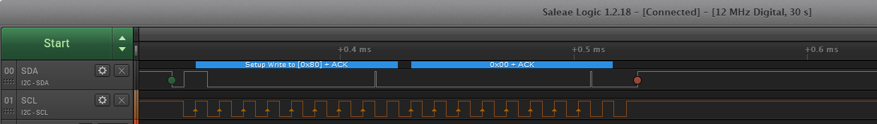
 In the evaluation, when they read temperature and humidity data repeatedly through I2C from HDC1080, the both data become 0xFFh rarely.

 I2C clock frequency is 400kHz.

 Could you tell me what could be the cause?

 Your reply would be much appreciated.

 Best regards,

 Kazuya.

  • Hi Kazuya-san,

    Do you have a logic analyzer capture of the I2C read that you can share?

    Additionally, what are the set conversion times?

    Best regards,

    Nicole

  •  Hello Nicole,

     Thank you very much for your reply.

     They are trying to get total I2C data logic capture or oscilloscope waveform of the 0xFFh reading case.

     I will send you the data as soon as I get it

     Also I confirmed they set configuration register to 0x00h.

     So I think each parameter setting should be as the follows.

     // Humidity MeasurementResolution = 14bit 

    // Temperature MeasurementResolution = 14bit

     // Mode of acquis = Temperature and Humidityare acquired insequence, Temperature first.

     // Heater = Heater Disabled

     // Software reset = Normal Operation


     Thank you again and best regards,

     Kazuya Nakai.

  •  Hello Nicole,

     The customer took some waveforms when temp and humidity data was 0xFFh as the attached.

     As a n additional information, one 0.1uF ceramic capacitance is placed jusy nearby HDC1080.  

     Could you please check their waveforms and give me your comment?

     Your reply would be much appreciated.

     Thank you and best regards,

     Kazuya.

    /cfs-file/__key/communityserver-discussions-components-files/1023/HDC1080_5F00_I2C_5F00_Waveform070720.pdf


  • Hi Kazuya,

    Thank you for the data.

    I believe the I2C stop condition is being violated, which can be seen in your 6th waveform image. In this capture the SCL line stays low while the SDA line transitions from low to high. To signal a stop condition SCL should be high while SDA is transitioning.

    Best regards,

    Nicole

  •  Hello Nicole,

     Thank you very much for your reply.

     I understood well what you said.

     Could I ask you a few additional questions as the follows?

     Q1. Is the stop condition needed to insert to the end of Frame 2 (Pointer register byte write timing)

           because we can't see the stop condition at the timing in figure 12 on page 12 of the device dtasheet?

     Q2. The customer is using figure 12 and figure 14 together to trigger measurement and measurement data reading as the follow.

           Frame 1 + Frame 2 (Figure 12) sending -> Wait 20ms for Temp/Humid measurement -> Frame 3 ~ Frame7 (Figure 14) sending using repeated start.  

           Is this sequence wrong to trigger measurement and read the measument data?

     Thank you again and best regards,

     Kazuya.


  • Hi Kazuya,

    A1. You're correct that figure 12 does not have a stop condition pictured, but a stop is usually issued after the measurement trigger command. A stop, or at least releasing the SCL line, is preferred to holding SCL low.

    A2. The sequence seems correct, but SCL is being held low and a stop would be preferred. 

    Best regards,

    Nicole

  •  Hello Nicole,

     Thank you for your reply.

     I asked them to try to change SCL lever to high and to check whether 0xFFh output phenomenon is solved or not.

     At this moment, they have a question as the follow. Could you please give me your reply?

     Q. Has TI ever seen this 0xFFh output phenomenon?

     Thank you again and best regards,

     Kazuya.

  • Hi Kazuya,

    Here was a similarly presenting issue regarding humidity readings with the HCD1080: https://e2e.ti.com/support/sensors/f/1023/t/621625?tisearch=e2e-sitesearch&keymatch=HDC1080

    In this scenario, increasing the conversion time to 100 ms seems to have resolved the problem.

    Best regards,

    Nicole

  •    Hi Nicole,

     Thank you for the information.

     I will ask them to try to read the temp and humid data after 40ms or longer wait time.

     But HDC1080 datasheet says like the follow on page 12 of the device datasheet.

    4. Read the output data:
    Retrieve the completed measurement result from register address 0x00 or 0x01, as appropriate, as shown in
    Figure 11. A read operation will return a NACK if the measurement result is not yet available, as shown in
    Figure 13 on page .

     According to their waveform, The acknowledge of Frame 3 is low and it means read data is active.

     Is my understanding wrong?

     Could you please give me your comment or advice?

     Thank you again and best regards,

     Kazuya.


  •  Hello Nicole,

     Thank you for your strong support.

     The customer read Temp/Humid data with 40ms wait time.

     But 0xFFh was still read.

     Do you have any idea to solve this 0xFFh reading problem?

     Thank you again and best regards,

     Kazuya.

  • Hello Kazuya,

    To answer your previous question

    Kazuya Nakai59 said:

    The acknowledge of Frame 3 is low and it means read data is active.

    Your understanding is correct that the SDA line being low in Frame 3 means read data is available.

    For further clarification, was the 40 ms wait time implemented in addition to issuing a stop after the Measurement Trigger?

    Best regards,

    Nicole

  • Hello Nicole,


     Thank you very much for your suppots.

     Yes. The customer inserted I2C stop condition before 40ms wait time .


     But 0xFFh data reading phenomenon was still observed.

    They checked VDD line whether any noise or surge is added on VDD power line or not.

    But any noise or surge was not observed.

     Also 0xFFh data reading phenomenon was observed on all HDC1080 units they checked.

    Could you please give me your idea or any countermeasure to solve the 0xFFh data reading?

    Thank you and best regards,

    Kazuya.

  •  Hello Nicole,

     I got several waveforms with stop condition addition and wait time extention as the attached.

    Could you please check the waveforms?

     Thank you and best regards,

     Kazuya.

    /cfs-file/__key/communityserver-discussions-components-files/1023/HDC1080_5F00_I2C_5F00_Waveform071320.pdf

  • Hello Kazuya,

    Would it be possible to extend the wait time to 100 ms and let us know if that resolves the issue?

    Best regards,

    Nicole

  •  Hello Nicole,

     Thank you for your reply. I see.

     But I got new information from the customer.

     I knew HDC1080 was connected to their controller via connector and about 50mm cable by information from the customer.

     Also I knew their waveform I sent you was taken at controller side not HDC1080 side.

     Now the customer is taking I2C waveform at HDC1080 SDA/SCL and GND terminals again.

     I will send you the waveforms as soon as I get those.

     Thank you again and best regards,

     Kazuya.


  • Nakai-san, 

    sounds good - also, if it helps here is example of the HDC1080EVM streaming data on the I2C bus. 

    /cfs-file/__key/communityserver-discussions-components-files/1023/HDC1080EVM_5F00_streaming_5F00_data.logicdata

    This can be viewed with Saleae PC GUI (from here) ==> https://www.saleae.com/downloads/

  •  Hello Josh,

     I couldn't find any VDD noise or I2C(SDA/SCL) signal noise on HDC1080 terminal when 0xFFFFh was read out as temperature and humidity data.

    The customer extended measument wait time to 100ms.

    But they confirmed that 0xFFFFh was read out several times in a day when the data was read out per one second. 

     Could you give me any countermeasure to resolve 0xFFFFh data reading out?

     Thank you and best regards,

     Kazuya.


  • Nakai-san - 

    I put this pdf together for the software/firmware flow needed for HDC10x0 devices. Would you please check it against your captures and firmware? 

    I think you will find the issue then. Here, just waiting 15mSec after starting the conversion before reading out the measurement results. 

    /cfs-file/__key/communityserver-discussions-components-files/1023/HDC1080_5F00_Software-Flow.pdf 

  •  Hello Josh,

     Thank you for the information.

     They tried to read the measurement result out with 20ms, 40ms 100ms waiting time. But in all case, 0xFFh data was read out rarely in a day.

     Their reading out sequence is the following.

      1. Start conversion (Start cond + 80h + Slave ACK + 00h+ Slave ACK + Stop cond)

      2. Waiting time (20ms, 40ms, 100ms)

      3. Reading out the measurement result (Start cond + 81h + Slave ACK + 0xFFh(Slave data) + Master ACK +x0FFh(Slave data) + Master ACK

          +  0xFFh(Slave data) + Master ACK +x0FFh(Slave data) + Master NACK +  Stop cond)

      They repeated 1~3 sequentially  per 1 sec.

      At 3th sequece, the acknowledge level from HDC1080 just after the data "81h" writing to HDC1080 was always LOW when x0FFh was read out.

     I think the acknowleage level means that the measurement data is ready. But the read data was x0FFh rarely.

     Have you ever heard this phenomenon from othe customers?

     Do you have any idea to resolve this phenomenon?

     Your comment or advice would be much appreciated.

     Thank you again and best regards,

     Kazuya.


  • Nakai-san, 

    Please ask them to provide a logic analyzer capture of this behavior. I think we are missing a detail in the communication between us here which will reveal itself, if we can see what the behavior is. 

    We recommend using a Saleae LSA (or similar), but if they don't have one, a two channel o'scope would also work. 


  •  Hello Josh,

     They got two waveform in 100ms wait time case as the attached.

     Also they got it using general oscilloscope because they don't have Saleae LSA.

     Could you please check the waveform and please give me your comment or advice?

     Thank you very much and best regards,

     Kazuya.

    /cfs-file/__key/communityserver-discussions-components-files/1023/HDC1080_5F00_I2C_5F00_Waveform073020.pdf

  • Nakai - 

    Thanks for the captures. 

    In the start conversion command capture you provide, the stop condition still looks to be violated and i was able to duplicate what you are seeing (at least the 0xFF 0xFF in the %RH registers) by just taking out the stop condition from my code after sending start conversion. To get as close to what I think I see in your scope captures. Fixing the I2C engine code in the MCU will resolve this. 

    Also, from your zoom, at 20uSec per division, it looks like the SCL is around 50kHz, not faster, as was previously mentioned earlier) - 

    So as first mentioned by Nicole, this is what the issue is (the lack of correctly formed stop condition from MCU), it has nothing to with any delay between start conversions and reading the registers (except ~15mSec is the min wait time, that must be respected)

  •  Hello Josh,

     Thank you very much for your comments.

     Could you please let me confirm whether my understanding is correct or not?

     I attached the corrected point for mesurement start command of my understanding as red color portion

    in the attached file.

     Is my understanding correct?

     Thank you and best regards,

     Kazuya Nakai.

    /cfs-file/__key/communityserver-discussions-components-files/1023/Corrected-waveform_5F00_080320.xlsx

  • Nakai - 

    Not quite - the Stop condition for I2C is defined as: 

    "A LOW to HIGH transition on the SDA line while SCL is HIGH defines a STOP condition."

    This is found on page 9 of the attached I2C spec, with the definition image. 

    /cfs-file/__key/communityserver-discussions-components-files/1023/I2C-Spec_5F00_UM10204.pdf

  •  Hello Josh,

     Could you please tell me the correct waveform for measurement start command?

     Please modify the excel file I sent previous to the correct waveform and please send me it.

     Thank you again and best regards,

     Kazuya.

  • Nakai-san, 

    Here is the correct waveform