This thread has been locked.

If you have a related question, please click the "Ask a related question" button in the top right corner. The newly created question will be automatically linked to this question.

TS5A22362: Propagation Delay

Part Number: TS5A22362

Hi,

We attend to use TS5A22362DGSR and TS5A23159DGSR on our circuit. For supply voltage, they are applied to 3.3V and 5V respectively.

I have two questions below.

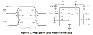
1. What the propagation delay for each?

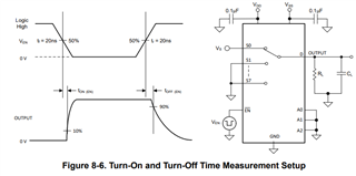
2. I saw two parameters: ton and toff, please help explain what do they mean? Whatis different between  ton/toff and propagation delay?

Thanks,

-bryant

  • Hi Bryant,

    Thanks for inquiring about the TS5A devices! 

    So for calculating propagation delay we actually have an FAQ specifically for this topic since some of our devices do not have propagation delay in the data sheet. [FAQ] How do I Approximate Propagation Delay and Channel to Channel Skew in an Analog Switch/Multiplexer?  

    As far as the difference between Ton, Toff and Pd the difference is as follows:

    Turn-on time is defined as the time taken by the output of the device to rise to 10% after the enable has risen past the 50% threshold. The 10% measurement is utilized to provide the timing of the device, system level timing can then account for the time constant added from the load resistance and load capacitance. Figure 8-6 shows the setup used to measure transition time, denoted by the symbol TON(EN)

    Turn-off time is defined as the time taken by the output of the device to fall to 90% after the enable has fallen past the 50% threshold. The 90% measurement is utilized to provide the timing of the device, system level timing can then account for the time constant added from the load resistance and load capacitance. Figure 8-6 shows the setup used to measure transition time, denoted by the symbol TOFF(EN)

    Propagation delay is defined as the time taken by the output of the device to rise or fall 50% after the input signal has risen or fallen past the 50% threshold. Figure 8-7 shows the setup used to measure propagation delay, denoted by the symbol tpd.

    Thanks!

    Alex