TMUX1119: DYNAMIC CHARACTERISTICS

Part Number: TMUX1119

Tool/software:

Hello,

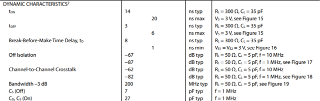
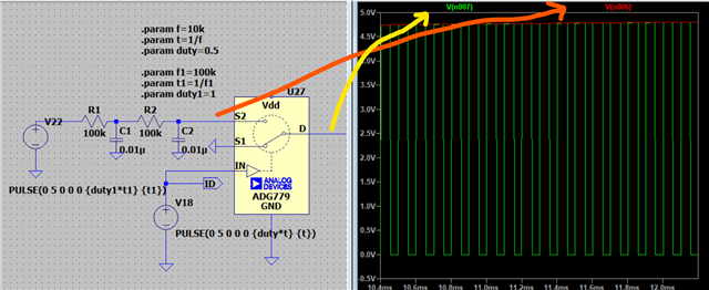
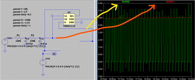
Please share "TMUX1119DCKR" turn on and turn off time as it doesn't mention into its datasheet. 

Thanks,

Krunal

  • See tTRAN and tOPEN(BBM).

  • Hello,

    i'm thinking to use "TMUX1119DCKR" IC as a alternate part of analog IC "ADG779BKSZ". In that datasheet they are providing data Ton and Toff. But couldn't find in this.

    Actually, i had a main question as i have simulation TI IC has ripple than analog IC. Can you share its cause of ripple appear into TI IC as TI IC has similar specification like analog IC?


  • Hi Alex,

    Sure. As per previous discussion, Nir suggest adding decoupling capacitor for filtering ripple. But i cannot change into PCB. So i need to understand direct drop in part. However, specification of TI IC is almost similar but i cann't differentiate its ripple behavior through datasheet and also with simulation. Even i have did board level analysis still ripple are there. 

    So that my question what causes ripple is generates at output and if possible, how to omit or minimize it.

    Regards,

    Krunal

  • Hey Krunal,

    I'm seeing the same transient spikes on my end in PSPICE. These should just be software behavior issues though; not something you would see in lab. However this statement : 

    Even i have did board level analysis still ripple are there.

    sounds like you're seeing the spikes on an IC level too? Do you have waveforms you can share here?

    In the meantime, I'm going to dig into this model and see where the issue lies. This is an older PSPICE model so the format is different than how we typically do it so it may take a little longer to sort through the code and see why the spikes are there though but I'll update you as I look into it and if I can find a solution to make the model run properly.
    In my simulations, I'm just putting a high impedance load on the Drain pin. is that close to what your system is looking like as well?

    Thanks,
    Rami

  • Hey Rami,

    Yes, I have did board level analysis. I have found also ripple into it. I have attached its waveform. 

    I have connected OPAMP before connecting a load in simulation and also same for board level analysis.

    Thanks,

    Krunal

  • Hey Krunal,

    What you're seeing in simulation is not the same as what you're showing me from the board level analysis. 
    The simulation looked like some spiking (probably some timing issue on the model side) on the rising/falling edges. This looks like noise when the signal is pulled high. Or even a poor ground on your oscilloscope. The mux behaves as an RC when the signal path is selected so it shouldn't be adding any noise. Is the arrow in the middle of the scope shot the expected voltage level? What voltage is that or what voltage are you applying? From simulation, it should be 5V supply with 5V square wave right? If you're actually seeing above 5V, which depending on your scaling it seems that you likely are seeing that, you could even be damaging the device. Can you share the x-y legend of the scope shot, with the time and voltage divisions shown?

    What op-amp are you using hereon your input?


    Thanks,
    Rami