This thread has been locked.

If you have a related question, please click the "Ask a related question" button in the top right corner. The newly created question will be automatically linked to this question.

TIDA-01471: Signal gain rate for 0.7Hz cutoff frequency?

Part Number: TIDA-01471

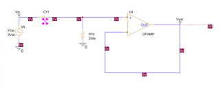
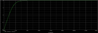
Hi' Another question I have is this. When I examined the Filter bode plot in the reference design, it was written that it guarantees 0.7Hz. When I analyzed the Bode plot graph with an  opamp these capacitor and resistor values , it was seen that it attenuated the signal by -2.4973dB at 0.7Hz. Don't we want the gain to be 0dB at 0.7Hz?   (-2.4973dB) isn't fold reduction a bad value for iepe sensor input in low frequnecies like 0.7  ?

Do you have any other suggestions to improve this? Increasing the filter order etc.

  • The simulation above is for the full signal chain. including the attenuation followed by the gain stages.

    the BW is the -3dB bandwidth as shown in the other figure

    you simulation is correct.

    - it is possible, with pretty stable filter transfer function over component variance, to compensate in the digital domain. so the varying filter gain could be brought to flatness in the digital domain.

    - another option is to increase your bandwidth so your band of interest falls in the 1dB bandwidth. in creasing filter order can be away to achieve that.

    it all depend on the frequencies you want to capture, and at which resolution.

    Regards,

    Ahmed

  • In other words, depending on the situation, we may need to digitally calibrate for different low frequency ranges or the filter degree may be increased. Thank you Ahmed!