This thread has been locked.
If you have a related question, please click the "Ask a related question" button in the top right corner. The newly created question will be automatically linked to this question.
Tool/software:
Hello everyone,
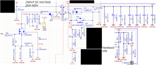
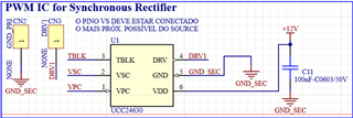
I am trying to test UCC24630 with a flyback operating with UCC38C40 on the primary side. It is a SMPS with a DC input voltage from 60V to 400 V and an output voltage equal to 12V/4A (UCC38C40 plus UCC24630) and 5V/1A (TPS 563208). My circuit schematic is in the comments bellow.
Resistor R27 was changed to 788k7, so the pin 1 (VPC) voltage is above the enable voltage (0.45V). I also used a 20 kΩ in R24 (time blanking resistor). R28 (gate-driver resistor) is a 50 Ω resistor.
I am following some component values in this reference design:
The SMPS is not working appropriately, because the voltage VREF is not in the appropriate range (4.9V - 5.1V according to UCC38C40 datasheet). It can be seen in the picture bellow in the channel 2 (green):
Here is another picture showing the voltage in the feedback pin of the UCC38C40:
I also got some results with UCC24630 that I’d like to show you guys, and maybe somebody could help me with this synchronous rectifier using ucc24630.
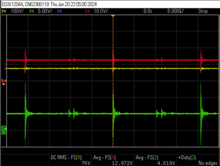
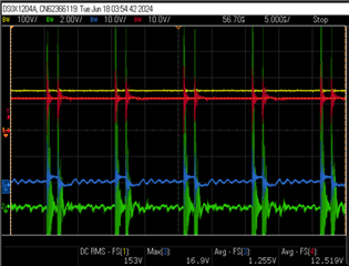
Here is the input voltage (ch. 1 - yellow), output voltage (ch.4 - red), VPC voltage (ch. 3 - blue), driver (ch. 2 – green):
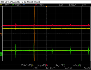
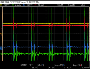
Here is the input voltage (ch. 1 - yellow), output voltage (ch.4 - red), VSC voltage (ch. 3 - blue), driver (ch. 2 – green):
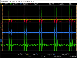
Here is the input voltage (ch. 1 - yellow), output voltage (ch.4 - red), VDD voltage (ch. 3 - blue), driver (ch. 2 – green):
Here is the input voltage (ch. 1 - yellow), output voltage (ch.4 - red) and the voltage on the third pin TBLK (ch. 3 - blue), driver (ch. 2 – green):
Any comments or suggetions regarding both ICs (UCC38C40 and UCC24630) would be of great help.
Thanks in advance.
Henrique.
Hello,
I am reviewing this inquiry and will get back to you shortly.
Regards,
Hello,
For security we handle all e2e threads on the e2e and not through email.
Regards,
I'll try to send the images here:
- Flyback topology:
- UCC38C40:
- UCC 24630:
Please let me know if it is clear.
Thank you.
Hello,
In regards to the UCC28C40 if VREF is lower than specifications. These devices are 100 % tested before they leave the factory. So this issue might be due to excessive loading of VREF or you have a layout grounding issue.
I reviewed the schematics that you sent and do not see anything unusual in them that would cause you issue. I believe if you resolve the VREF issue this resolve your regulation issues.
The UCC24630 works on volt second balance. However, for trouble shooting purposes I would disable the SR FET and use the FETs body diode for rectification. Once you get the UCC38C40 design working then you can work on getting the UCC24630 SR driver to work.
The UCC24630 has an excel design tool that you can use to setup it up once you have the flyback converter is operating correctly. You can find it at the following link.
https://www.ti.com/tool/download/SLUC582
The UCC28C40 is actually handle by another applications engineer. If you have any further questions or need further help with the UCC28C40 please repost in the e2e with the UCC28C40 in the thread title? This is so the appropriate applications engineer can help answer your questions and help you with any issues that you might have with this controller?
Regards,
Mike O',
Yes, I checked the voltage in the VREF pin and it is ok (5V). I was confused because of my probes that caused a voltage reduction in the measurement.
I'll post again in the UCC38C40 because the output voltage should be 12 V but it is slightly changing with load variation. Thanks for your support.