This thread has been locked.

If you have a related question, please click the "Ask a related question" button in the top right corner. The newly created question will be automatically linked to this question.

TIDA-010042: HIN and LIN signal from msp430f5132 is sometimes becoming high simultaneously during switching

Part Number: TIDA-010042
Other Parts Discussed in Thread: MSP430F5132

Tool/software:

Hi,

In TIDA-010042(msp430f5132 based design), I have changed the timer D mode from up mode to up/down mode .The reason for change was to enable deadband (312ns) on both sides of pwm signal.

Now we are facing two issues:

1.During Buck enable after disabling, a high current is flowing.

Currently only one phase is enabled in interleaved.

Fullscreen
1
2
3
4
#define BUCK_DISABLE TD0CCTL1 = TD0CCTL2 = OUTMOD_0;\
TD1CCTL1 = TD1CCTL2 = OUTMOD_0; // Turn PWM outputs off
#define BUCK_ENABLE TD0CCTL1 = OUTMOD_6;\
TD0CCTL2 = OUTMOD_2;
XXXXXXXXXXXXXXXXXXXXXXXXXXXXXXXXXXXXXXXXXXXXXXXXXX

When we analysed the signals and we found that high side and low side signal from microcontroller is becoming high causing both fet to turn on at the same time.Please see the attached screenshot of waveform of SW node during this time.

Yellow- 3.3V(ground bouncing), Blue-SW Node

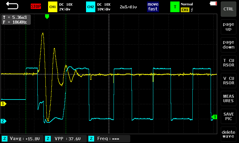
2.We tried full time enabling of buck(no disabling)- By this modification, the issue was almost gone, but even after that at sometimes, the issues comes again.

Please see the attached screenshot of waveform of high and low side signal from microcontroller during the issue.

Yellow is high side signal and blue is low side signal

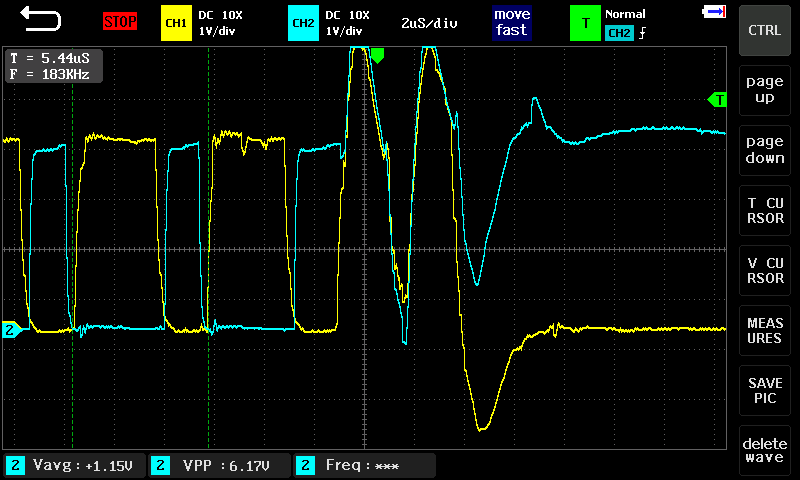
Do you know what may be the reason for this?

Regards,

Cyril

  • Hi Cyril,

    Do you use isolated probe when testing the upper FET's PWM signal?

    Also, I had not changed the carrier counting mode when doing test...

    Regards,

    Bowen

  • Hi Bowen,

    I am not sure why you asked for isolated probes. The waveform shown above is output from msp430 and not the driver.

    Also, do you mean up mode for carrier counting mode. I had used up/down mode to introduce dead band on both sides of pwm signal.

    Regards,

    Cyril