Part Number: CC2745R10-Q1
Tool/software:
Issue:
When trying to flash or debug a CC27XX using CCS 20.3.0, the following error is reported:
Cortex_M33_0: Flash loader: CC23xx_CC27xx_FLASH_LIBRARY_VERSION 4.1.0.141
GEL: Error while executing OnPreTargetConnect(): Secure Debug Manager library not loaded!
         at GEL_LoadSecureDebugManager()
         at GEL_EvalOnTarget("CS_DAP_0", "GEL_LoadSecureDebugManager()") [cc23xx_xds.gel:81]
         at OnPreTargetConnect()
Error connecting to the target: (Error -2001 - (0:20:0)) Internal error: Invalid parameter passed to function. Restart the application. If error persists, please report the error. (Emulation package 20.3.0.3656)
GEL: Error while executing OnRestart( 0 ): Connect failed
         at GEL_Connect() [cc23xx_connect_util.gel:41]
         at ConnectIfDisconnected() [cc23xx_xds.gel:101]
         at OnRestart(0)
AutoRun: Unable to run the target at this time
AutoRun: Target not run as breakpoint could not be set: Cannot enable while the target is disconnected
Target is not connected
This is due to the Secure Debug Manager dll included in this version of CCS is missing some dependencies.
Fix:
SecureDebugManagerCC27_win.zip
Download the zip file, extract it and replace the content at <ccs_install>/ccs/ccs_base/DebugServer/bin/sdm/
Part Number: CC2340R5
Tool/software:
Hi all!
For those that have installed the new SimpleLink Low Power F3 SDK 9.10.00.83 (for devices CC23xx and CC27xx) you may have noticed the folder structure for the Bluetooth Low Energy (BLE) stack changed. This means that projects created before SDK 9.10 have different source/example folder paths than previous SDKs. It's important to keep this in mind when migrating to the 9.10 SDK, since many paths will be broken on older projects.
The folder containing source files for the BLE stack is no longer source/ti/ble5stack but now source/ti/ble. You will also find that examples for BLE are no longer under examples/rtos/ble5stack but now examples/rtos/ble.
We have created a migration guide for those migrating to the newer SDK and you can find it here.
Thanks!
The TI BLE Applications Team.
Part Number: CC2340R5
Tool/software:
Hello!
A new Simple Link Academy (SLA) lab is now online! Bluetooth Low Energy (LE) and Drivers.This hands-on lab covers the basics of how to build a project that involves using TI developed driver functionalities on top of the basic_ble project. The lab activities walk you through how to use drivers like GPIO, ADC, LGPTimer, Systerm Timer, and Real Time Clock (RTC) while also enabling Bluetooth Low Energy to transmit data from a peripheral device configured as a server.
Please fill free to take a look at it here (dev.ti.com). Bluetooth Low Energy (LE) and Drivers: https://dev.ti.com/tirex/explore/node?node=A__AdJGGjMzkV-9BzOpn3MnQQ__SIMPLELINK-ACADEMY-CC23XX__gsUPh5j__LATEST
Best Regards,
David.
Part Number: CC2340R5
Tool/software: CCS Theia
Code Composer Studio is transitioning to Theia from Eclipse
Theia is an open-source initiative to provide a VS Code® “like” application framework
Why should you adopt CCS Theia?
to CCS Theia is straight forward (see below)
Why Theia instead of VS Code®?
How to migrate?
and Theia
What about CCS Cloud?
How to get started?
Note: This post only announces the availability of CCS Theia for the CC23xx devices (including CC2340R5 and CC2340R2). The deployment timeline of CCS Theia is different across TI portfolio. Reference the release notes of the SDK applicable to your product for more details on the applicable timeline.
Part Number: CC2340R2
Tool/software:
Hello!
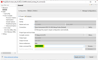
In order to migrate a project developed for CC2340R5 to CC2340R21 or from CC2340R5 to CC2340R22, please follow CC2340R5 to CC2340R21 Porting Guide and CC2340R5 to CC2340R22 Porting Guide respectively. However please take note that there is no need to modify the Flash size and RAM size in the linker command file as suggested in the migration guide (see Step 5) as these values are updated by the GenMap feature inside the lpf3_app_freertos.cmd (see GenMap).
However, it is important to consider that the new linker command file that is generated after migration - cc23x0r2.cmd (see image below) has to be excluded from build so that the original lpf3_app_freertos.cmd is used. This is especially important for OAD related projects, as the new cc23x0r2.cmd file does not include the OAD symbols and will not build correctly.
In addition, although the Heap Size depends on the RAM size consumed by your application, we suggest to start with a lower value than the one suggested in the Migration Guide (see Step 6), for instance: 0x0003400.
Hope this helps!
Part Number: CC2340R5
Dear users,
IAR Embedded Workbench users are recommend to use IAR 9.40.2 with F3 SDK 7.40.00.64. This information has not been properly reported in the release notes of the SDK.
Using previous IAR versions may lead to issue during the launch of debugging sessions.
So far, no issue have been reported while using newer IAR versions (such as 9.50.2).
Appreciate your comprehension.
Best regards,
Part Number: CC2340R5
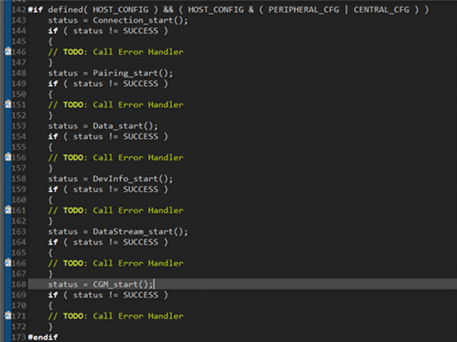
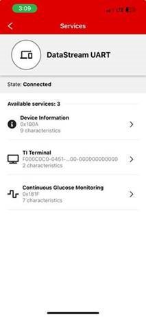
The purpose of these instructions are to detail how to merge/add multiple BLE profiles into a single project. The following is an example which uses the "data_stream_UART_over_BLE" as the base project and the "basic_ble_profiles" project as a source for the addition of the Continuous Glucose Monitoring (CGM) profile.
Importing Projects:
Copying & changing necessary files:
Ensuring correct functionality:
As shown in the steps above, you can take the files for an existing profile and copy them over to another project to utilize the profile and keep the project's original functionality. For any additional questions or issues with this process, please open a new thread.
This guide shows how to use SDK Composer so the size of the SDK downloaded and installed is reduced.
This guide applies to the devices supported by the SimpleLink Low Power F2 SDK (CC13x1, CC13x2, CC13x4, CC26x1, CC26x2 and CC26x4) and SimpleLink Low Power F3 SDK (CC23xx).
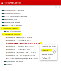
1- Open https://dev.ti.com/tirex/. This web-page centralizes the development resources (SDK, training, documentation, etc.) for all the TI devices.
2- Unroll the "Wireless connectivity" > "Embedded Software". This should display several SDKs. Hover over the SDK applicable to your device, click on the three dots and on "Download".
The screenshot below shows the procedure for the Low Power F2 SDK.
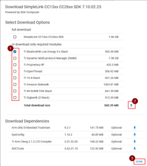
3- A pop-up is displayed and invite you to select the components you need.
Select the components you want (this automatically deselect the full download). Once done, click the download icon and eventually the "Done" button.
The screenshot below shows how to create
4- This should automatically start the download of a zip file.
5- Extract the content of the zip file inside the C:\ti folder
6- The SDK is ready to be used!
Tip: In the SDK installation folder, the docs and examples folders can be deleted to save more space.
I hope this will help,
Part Number: LP-EM-CC2340R5
The following details how to modify the uart2echo SDK example to enable the event Mask, and event Callback overrun on the LP-EM-CC2340R5.
Summary:
By implementing the following code snippets into your uart2echo example you will be able to detect when an overrun event has occurred, track the total overrun events, and see a green LED toggle as the overrun events occur.
Steps:
/* Declare global variables */
uint32_t glostat = 0; //stat to check the total numver of overrun events
uint32_t glostatnot = 0;
uint8_t uhOh = 0; //flag to check if overrun event has occurred
4. Setup the green LED config in a similar manner to the red LED
GPIO_setConfig(CONFIG_GPIO_GLED, GPIO_CFG_OUT_STD | GPIO_CFG_OUT_LOW);
5. In the mainThread in the uartParams section (before UART is opened) define the eventCallback and eventMask.
    uartParams.eventCallback = eventcallbackFxn;
    uartParams.eventMask     = UART2_EVENT_OVERRUN;
6. Setup the eventcallbackFxn, this function will occur when an overrun event has occurred and will toggle the green LED as well as tracking the current total number of overrun events by incrementing glostat; we will also change the state of the uhOh flag to indicate that an overrun event has occurred (to be used later).
/*
 * ======== eventcallbackFxn ========
 */
void eventcallbackFxn(UART2_Handle handle, uint32_t event, uint32_t data, void *userArg)
{
    if (event == UART2_EVENT_OVERRUN) //check if the event is overrun event
    {
        //UART2_flushRx(uart);
        glostat++;
        uhOh = 1;
        GPIO_toggle(CONFIG_GPIO_GLED); //if its valid this should still work.
    }
    else
    {
        glostatnot++;
    }

}
7. In mainThread, in the while(1) loop add the following code, this code will clear the FIFO buffer when a certain number of bytes is read, or when an overrun event is detected (by the uhOh flag).
 if(numBytesRead > 64)
{
    UART2_flushRx(uart);
}
if(uhOh)
{
    uhOh = 0;
    const char overrunPrompt[] = "\r\nOverrun Event Occurred, clearing RX buffer:\r\n";
    UART2_write(uart, overrunPrompt, sizeof(overrunPrompt), NULL);
    UART2_flushRx(uart);
}
8. Build, load, and run the program, use PuTTY to connect to the device, and by entering too many characters you will see the overrun event execute, and see the green LED toggle on your board.
This example was evaluated on the 7_40_00_64 SDK, on CCS 12.5.
Part Number: CC2642R
Hi,
Here are some steps to enable synchronization with a periodic advertising train on CC2642R, CC2652R or CC2652R7.
This guide assumes you are using the simple_central example for the device selected. This guide has been tested on SDK 7.10.00.98.
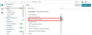
1- Enable support for "Periodic Advertising Sync"
2- Save and close SysConfig
3- In SimpleCentral_processGapMsg(), under GAP_DEVICE_INIT_DONE_EVENT, ensure the GAP layer does not filter out the advertising packets you are interesting into. Commenting out the line "temp16 = SCAN_FLT_PDU_CONNECTABLE_ONLY | SCAN_FLT_PDU_COMPLETE_ONLY;" and replace by "temp16 = SCAN_FLT_PDU_NONCONNECTABLE_ONLY;".
4- (Optional) Automatically trigger scan operation by adding the following code at the end of the case GAP_DEVICE_INIT_DONE_EVENT in SimpleCentral_processGapMsg():
      // Automatically trigger scan
      GapScan_enable(0, 0, 0);
5- Add the code to create a sync with a received advertisement. The following code should be added in SimpleCentral_processAppMsg() within the case "SC_EVT_ADV_REPORT":
      GapScan_Evt_AdvRpt_t* pAdvRpt = (GapScan_Evt_AdvRpt_t*) (pMsg->pData);

//// BEGIN
      if(0 != pAdvRpt->periodicAdvInt)
      {
          // this is a periodic advertisement
          GapScan_PeriodicAdvCreateSyncParams_t pSyncParams;

          pSyncParams.options = SCAN_PERIODIC_DO_NOT_USE_PERIODIC_ADV_LIST |
                                SCAN_PERIODIC_REPORTING_INITIALLY_ENABLED;
          pSyncParams.advAddrType = (uint8)pAdvRpt->addrType; // only ADDRTYPE_PUBLIC and ADDRTYPE_RANDOM are allowed
          osal_memcpy(pSyncParams.advAddress, pAdvRpt->addr, B_ADDR_LEN);
          pSyncParams.skip = 0; // should be between 0 and SCAN_PERIODIC_SKIP_MAX
          pSyncParams.syncTimeout = 1000; // synchronization timeout for the periodic advertising train is 1000*10ms = 10s
                                          // should be between SCAN_PERIODIC_TIMEOUT_MIN and SCAN_PERIODIC_TIMEOUT_MAX
          pSyncParams.syncCteType = SCAN_PERIODIC_CTE_TYPE_ALL;

          uint8_t status = GapScan_PeriodicAdvCreateSync(pAdvRpt->advSid, &pSyncParams);
          if(SUCCESS != status){
            // handle error
          }

          GapScan_disable("");

          break;
      }
//// END

      //Auto connect is enabled
6- Declare a volatile global variable to count the advertisements received.
volatile uint32_t numberOfReports = 0;
7- In SimpleCentral_processGapMsg(), add the handling for the cases GAP_SCAN_CREATE_SYNC_EVENT, GAP_SCAN_PERIODIC_ADV_SYNC_EST_EVENT and GAP_SCAN_PERIODIC_ADV_REPORT_EVENT:
    case GAP_SCAN_CREATE_SYNC_EVENT:
    {
        GapScan_PeriodicAdvEvt_t *pPkt = (GapScan_PeriodicAdvEvt_t *)pMsg;
        uint8_t status;

        if(pPkt->status == SUCCESS)
        {
          status = GapScan_enable(0, DEFAULT_SCAN_DURATION, 0);
          if(SUCCESS != status){
            // handle error
          }
        }
        break;
    }

    case GAP_SCAN_PERIODIC_ADV_SYNC_EST_EVENT:
    {
      GapScan_Evt_PeriodicAdvSyncEst_t *pPkt = (GapScan_Evt_PeriodicAdvSyncEst_t *)pMsg;
      uint8_t status;

      if(pPkt->status == SUCCESS)
      {
        status = GapScan_SetPeriodicAdvReceiveEnable(pPkt->syncHandle, 0x01);
        if(SUCCESS != status){
          // handle error
        }
      }

      break;
    }

    case GAP_SCAN_PERIODIC_ADV_REPORT_EVENT:
    {
      GapScan_Evt_PeriodicAdvRpt_t *pPkt = (GapScan_Evt_PeriodicAdvRpt_t *)pMsg;

      numberOfReports++;

      // Free report payload data
      if (pPkt->pData != NULL)
      {
        ICall_free(pPkt->pData);
      }

      break;
    }
8- Build and Flash the device
9- Turn on the periodic advertiserdevice
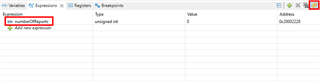
10- Run the program in debug mode. Ensure the variable numberOfReports is added to the "expressions" view.
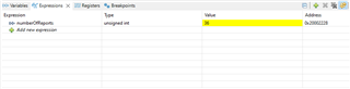
11- The device synchronizes and reports the advertising events:
Note: If you have enabled automatic scan start (step #4), there is no action to be made. If you haven't enabled automatic scan start then you should use the two-button menu to trigger the scan.
Note 2: Even if you have enabled automatic scan start (step #4), you may have to repeat the operation using the two-button menu.
Please also check this thread showing how to set-up CC2642R or CC2652R7 devices as periodic advertiser: https://e2e.ti.com/support/wireless-connectivity/bluetooth-group/bluetooth/f/bluetooth-forum/1294888/faq-cc2642r-periodic-advertising-with-cc2642r-cc2652r7
I hope this will help,
Best regards,
