
We are planning to use the ADS7254 in a design that will sample one differential signal and one single ended signal. Would we be able to attach the minus input to GND of the single ended signal? The exact inputs are listed below.
…We are planning to use the ADS7254 in a design that will sample one differential signal and one single ended signal. Would we be able to attach the minus input to GND of the single ended signal? The exact inputs are listed below.
…Hi Ryan,
Thank you for your confirmation. I hope that the datasheet will be revised soon.
Regards,
Uchikoshi
Hello Uchikoshi-san,
Please use the table as written in the data sheet to indicate the clock falling edge on which the DOUT bit changes. The next clock rising edge should be used to latch this bit by the host controller.
Regards,
Hi Ryan,
Can I get any feedback from you? I have to update it to customer.
Regards,
Uchikoshi
Hi Ryan,
Thank you and understand the clock timing. Please let me know once you can confirm about figure 91.
Regards,
Uchikoshi
Hello Uchikoshi-san,
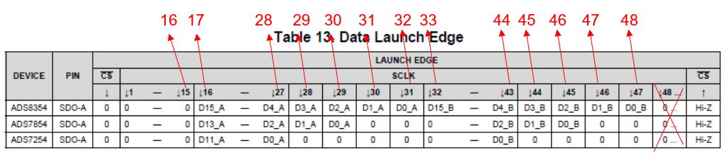
I misspoke in my previous reply. When I said "the customer will read data on the next SCLK edge" I meant to say rising edge. You are correct that data cannot be launched and read on the same edge. Table 13 lists the falling…
Hi Ryan,
Thank you for your reply. I am still confusing. This is SPI interface and clock master is MPU(ADS7254 is SPI slave). The point is at which falling clock edge MPU needs to sample the data. For bit "D15-A", figure 91 shows it is 17th falling edge…
Hello Uchikoshi-san,
Thank you for your post.
The Data Launch Edge tables indicate when the data is changed on the corresponding SDO pins. The customer will need to read the data on the next SCLK edge after the bit is changed. So, if data bit 15 is launched…
Hi Experts,
There is a data timing table on page 39. The SCLK timing looks shifted. I am expecting that below is the correct.
Could you please confirm it?
Regards,
Uchikoshi
Vidhi,
Below thread explains how to transmit 32 bits at a time. When are trying to read the SPI data received from ADC. You need to wait for
RXFFINT flag to be set and then read the SPIRXBUF register can be used to read the results stored in FIFO

Regards…
Hello,
I changed the GPIO60 to GPIO56 and I read correct value from ADC, but I can read sometimes and most of the time no. So, I decided to do what you suggested Ryan.
The clock is of 48 pulses with the following dma configuration. So, I do not think…
Hi Vidhi,
Do you mean that the SPI peripheral can only support 16-bit frames or 16-bit word sizes? I'm not familiar enough with the TMS320F28379D to say what the supported frame lengths are, but I imagine that it's possible to send more than two bytes…
Hello sir,
Thank you for the reply. I am new to SPI, and hence How can I transfer 32 bit for the first time using FIFO ?
as SPI can only send 16bit.
Hello Vidhi,
The CFR register value 0x8800 is the correct value for writing to the register with the desired settings mentioned in your first post. However, the ADS7254 defaults to 32-CLK, dual-SDO mode upon power-up. To change the mode, the first command…
Thank you for the response.
yes I am reading ADC value. I am sending 0x8800 to ADC. I am monitoring SPI buses and they seems correct.
When I observed SOMI, it is 0 when there is clock as shown in the photo attached. The picture is taken when sent dummy…
Vidhi,
Based on the inputs provided, I believe you just trying to read ADC results on the falling edge of SPICLK correct?
Looking into ads7254 DS, it looks like you need to do the following:-
1) Write CFR = 0x8800 to select 16-CLK,Dual-SDO Mode), this…
Dear sir/Madam,
I am using ads7254 external ADC with LaunchPad TMS320F28379D using SPI. I have tried the loopback example and works correctly. but when I load configuration with ADC…
Hello Zhihong,
Thanks for your post. Please find the parametric search results here.
Based on your comment in the last bullet, it sounds like the customer is also expecting to use the exact same register settings. Is that correct? I don't believe this…
Hi Wesley,
Yes, CFR.B7 MUST be set to 0 in the ADS7254. This is not optional. Please ask your customer to read the Configuration Register (CFR) description on page 34.
Best regards,
Hello Wesley,
Thank you for your post.
I would not suggest treating the register maps in the ADS7253 and ADS7254 similarly. The ADS7254 only supports fully-differential inputs and bit 7 of the CFR register must always be 0.
Best regards,
Hello Uchikoshi-san,
The design team has provided some additional feedback. They do not expect any damage to the device when AVDD is powered without DVDD. The customer may observe marginally higher current from AVDD to GND and the interface will not work…

