This thread has been locked.

If you have a related question, please click the "Ask a related question" button in the top right corner. The newly created question will be automatically linked to this question.

INA219: INA219 accuracy error

Part Number: INA219
Other Parts Discussed in Thread: INA226

Hi,

Design Details:

Rshunt = 0.01ohm (CRF0805-FX-R010ELF, circled in schematic)

Max Expected Current = 4A.

Bus Voltage = 7.5V

CALIBRATION: 0x0FFF

CONFIG: 0x27FF

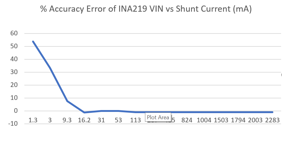
So current sensitivity for 1 LSB is 1mA.  But I always seem to have an offset of ~20mA.  In PCB layout we have a good kelvin connection to the resistor (CRF0805-FX-R010ELF).  Attached is a graph of the accuracy we are getting.  I've measured it using two different methods (power supply across shunt / electronic load), its always the same.  I've even taken D3 out (see attached schematic) of the circuit to ensure nothing else is downstream is drawing power.

Also, one more interesting clue is that the offset tracks the bus voltage.  So, I can get to a 0mA reading when VBUS = 0V.  It seems like there is a resistive load on IN- to ground except my power supply current is reading 0mA?!  Maybe the part is damaged? 

Any ideas?

Thanks!

Erik

  • Oh and when the board is not powered, I measure high impedance at IN-.  So there isn't an actual load resistance on IN-, but it looks like there is when the device is powered on.  And I should also mention that this issue occurs on all boards I've tested so far.

  • Hi Erik,

    As a first step, I would replace R20 and R33 with 0Ohm, there should be large improvement in the offset current.

    It is unlikely that you got a damaged part, although it is a possibility.

    Regards, Guang

  • Great idea.  Actually I see now that 10ohms * 20uA input bias = 0.2mV.  And so trying to sense even 100mA through my 0.01ohm shunt would only give 1mV.  So, that is ~20% error from input bias current which is close to the accuracy error I am seeing at 100mA.  I will try it tomorrow with 0ohm stuffed instead of 10ohm.  Thanks for the quick reply.

    Erik

  • Hi Erik,

    You’re welcome; please confirm your findings once the experiment results are available.

    Regards, Guang

  • Yes, it looks like replacing the 10ohm filter resistors with 0ohms improves things a lot!

    I think the remaining error is just the INA219's offset (10uV max at PGA gain /1).  We are trying to measure down to 1mA resolution through a 0.01ohm resistor which is a 10uV drop.  This should be acceptable for us, I guess we could double the resistor to 0.02ohm to help drown out the offset of the part a bit more.

    Thanks for the help, I think there should at least be a note in the datasheet that states how these 10ohm filter resistors can cause significant accuracy errors at lower currents.

    Erik

  • Hi Erik,

    You’re right that at that low level of current, device intrinsic offset starts to dominate even though INA226 has excellent accuracy spec. As you noted, one solution is to increase the shunt value as long as it doesn’t cause shunt voltage over range, at the same time resistor power rating is considered.

    Your suggestion about a note is taken. Thank you

    Regards, Guang

  • Hi Erik,

    I think your question has been answered, and will close this thread. Please confirm or let us know if further assistance is needed.

    Regards, Guang