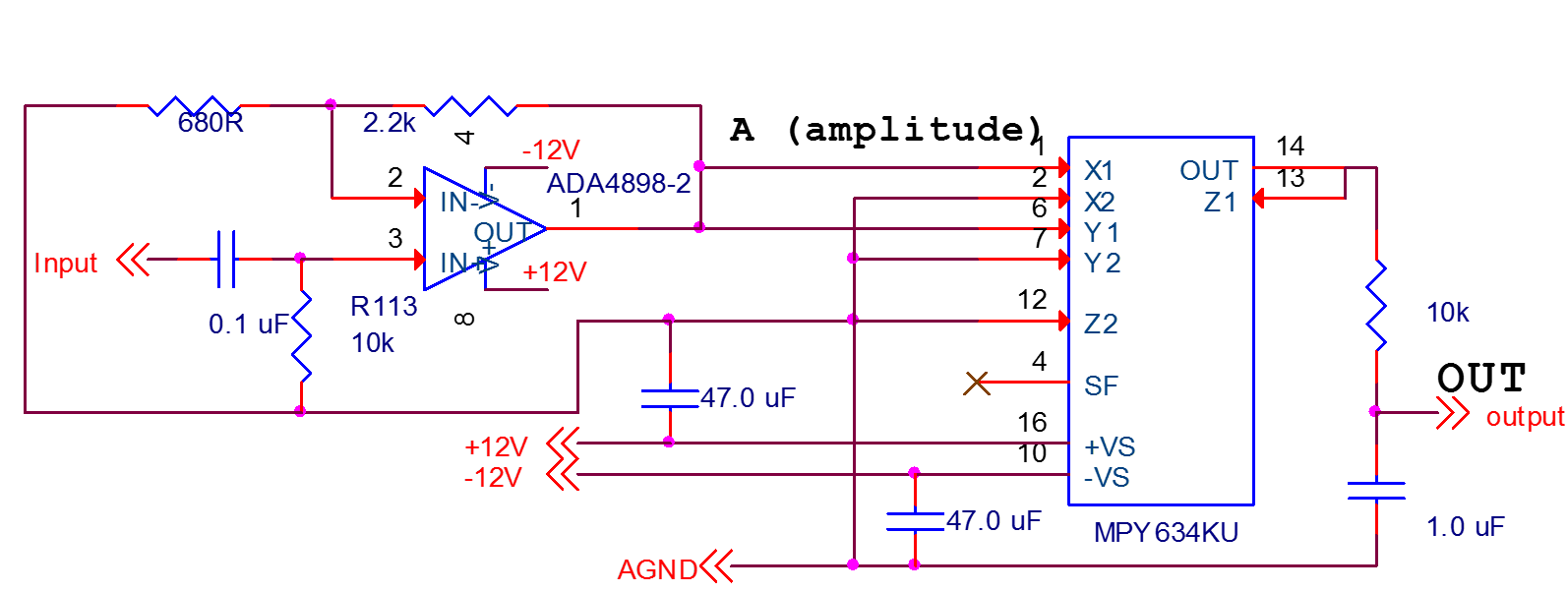
We attempted to use MPY634 as a wide-bandwidth multiplier, but detected that it had a boost with frequency.
In order to recheck it we have bought directly from TI some more MPY634 chips and assembled a prototype board , and have seen quite the same results.
Is there any mistake here?
Thanks in advance
Oleg
|
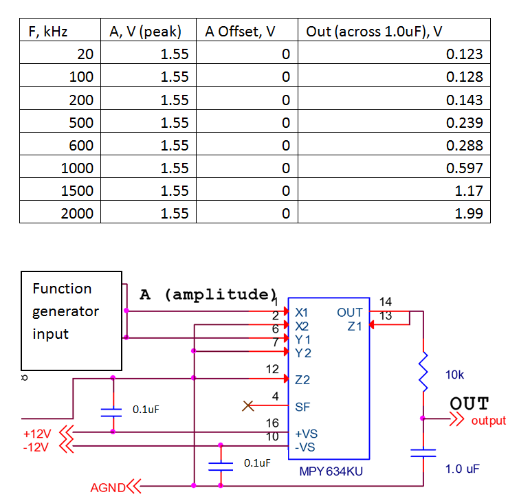
F, kHz
|
A, V
|
OFFSET, V
|
OUT, V
|
OUT (theory)
|
|
20
|
1,55
|
0,05
|
0,134
|
0,120125
|
|
100
|
1,55
|
0,04
|
0,138
|
0,120125
|
|
300
|
1,56
|
-0,04
|
0,18
|
0,12168
|
|
600
|
1,53
|
0,08
|
0,296
|
0,117045
|
|
1000
|
1,5
|
0,04
|
0,536
|
0,1125
|
|
1500
|
1,44
|
0,04
|
0,852
|
0,10368
|
|
2000
|
1,35
|
0,04
|
1,12
|
0,091125
|
|
F, kHz
|
A, V
|
OFFSET, V
|
OUT, V
|
OUT (theory)
|