This thread has been locked.

If you have a related question, please click the "Ask a related question" button in the top right corner. The newly created question will be automatically linked to this question.

WEBENCH® Tools/LMK03328: peak to peak jitter

Part Number: LMK03328

Tool/software: WEBENCH® Design Tools

Hi Zoe and technical support team

I have related question about following E2E.

https://e2e.ti.com/support/clock-and-timing/f/48/t/711966

I tried Zoe's .mac(changed .pdf) you have adjusted RMS jitter with LMK03328EVM.

e2e.ti.com/.../4174.LMK03328_5F00_rev2.pdf

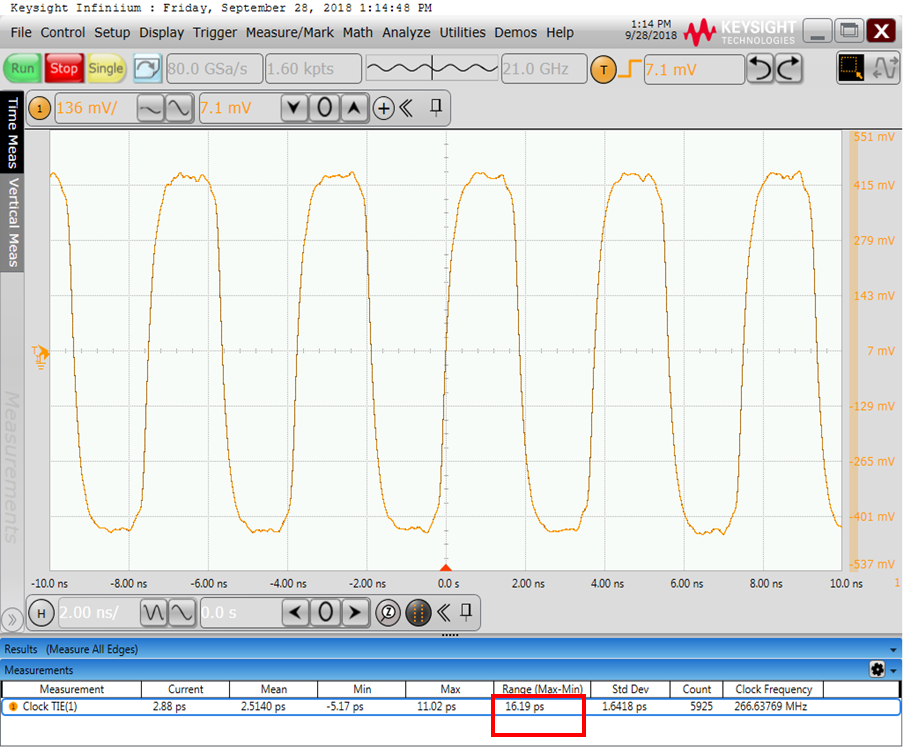
My waveform is below and red circle is peak to peak jitter(16.19ps).

When you tried it , RMS jitter shows 156.864fsec(peak to peak jitter 1.167ps(156.864x7.44). It is lower than my result.
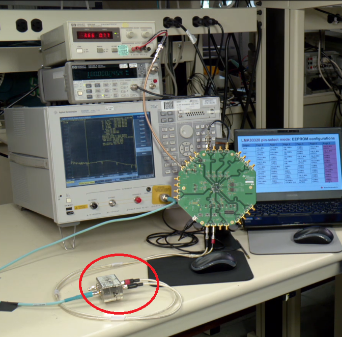
【My environment 】

Power supply: Metronix 545c(old product) → 5V  for J3pin.

OUT7P/N → 100Ω for R75 . I probe on R75.

External Cap for Loop filter → 0.003uF for fraction

Best Regards,

ttd 

Best Regards,

ttd

  • Hello ttd,

    Are you able to make a direct connection from SMA connector to scope without using probe? Then clear statistics and check p2p after 5000 cycles?

    Also, which scope are you using? Looks like a Keysight Infiniium -- what is the model number?

    If you configure your reference for the same output frequency as the LMK03328 output and measure p2p jitter, what is the result?

    73,
    Timothy
  • Hi Timothy,

    Thank you for your reply.

    I'd like to try your advice.

    ■Oscilloscope

    Keysite : DSAZ204A

    → I used TIE function of oscilloscope. 

         See attached URL , page 9.

         file:///C:/Users/090727/Downloads/AN10007-Jitter-and-measurement%20(2).pdf

    ■Probe

    How do you connect SMA cable between EVM and oscilloscope?

    Do you connect two SMA of EVM to 2ch of Oscilloscope and calculate differential range on software of Oscilloscope?

    Video of LMK03328EVM show that something change from differential to single .

    Does it trans? Could you show product number of that?

    https://www.youtube.com/watch?v=_J3H2U-FWtY

    By the way, I designed my board and it doesn't have SMA connector.

    So I use differential probe to check jitter.

    If you have any important point , could you share it?

    【background】

    DDR4's spec is very strict below. It specified 10ps p2p (BER 10-12) 

    So RMS jitter(st div) x 14.069 = peak to peak jitter.

    TI's evaluation result, RMS jitter shows 156.864fsec for 266.625MHz.

    So RJpk-pk = 156.864 fsec x 14.069 =2.2ps

    It seems to be satisfied with DDR4 spec of 10ps (p2p).

    Best Regards,

    ttd

  • Hello ttd,

    The differential to single ended converter appears to be a Macom H-183-4, a hybrid mixer. You terminate one port with 50 ohms, and then use the 0 & 180 degree ports for the differential side with the single ended side being either 0 or 180.

    I understand your situation for the probing vs. SMA.

    Are you able to probe the reference?

    73,
    Timothy
  • Hi Timothy,

    Thank you for your reply.

    Which is better for precision jitter measurement , the differential probe or SMA with hybrid mixer?

    Does "the reference" mean input reference clock "50MHz oscillator " on EVM?

    Best Regards,
    ttd
  • Hello ttd,

    Yes, by reference, I did mean the 50 MHz oscillator on the EVM. I was hoping to establish a baseline of measurement performance by this test. Is this 50 MHz from an XO?

    --

    As for diff probe or SMA + differential to single ended conversion...
    I would say SMA with the hybrid mixer (or other differential to single ended conversion) is better. Note, you can make measurements without differential to single ended conversion, but you may see more spurs that way because you won't have differential immunity.

    The reason I say SMA because it wouldn't be subject to possible impact by hand probing. Also, you presumably with an SMA connection you would be going from source --> load where the load is the measurement equipment. With the probe, you have a high impedance which is 'sniffing' the signal. I think you can make good jitter measurements using the probe approach, but more care must be taken. It is best if you can use a solder in differential probe. Is your differential probe solder in or browser type that you are manually holding?

    I did some testing, I do have some setting I'd like you to try...
    * Please try reducing the PLL1 fraction. Instead of 325/1000, try using PLL1_NUM = 13 and PLL1_DEN = 40. See if that improves your performance.
    * Another testing idea would be to reduce the PLL1 charge pump gain from 1.6 mA to 0.4 mA.

    73,
    Timothy