This thread has been locked.

If you have a related question, please click the "Ask a related question" button in the top right corner. The newly created question will be automatically linked to this question.

OPA2188: Simulation and Test Circuit output mismatch

Part Number: OPA2188
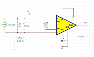
Other Parts Discussed in Thread: TINA-TI, OPA4188, INA333, INA827

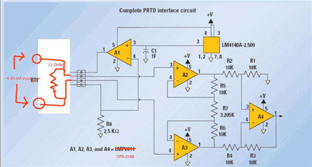
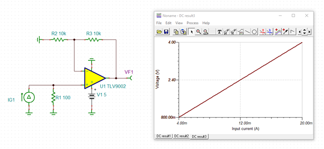
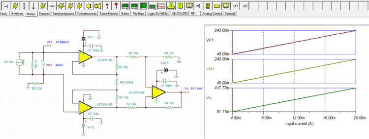
I have tried RTD Simulator reference design SNOA838 with replacing OPA2188 which works pretty good in simulator as well as test Circuit. When I try to Convert same circuit for Current Measurment 4-20mA I found it work good with TINA Simulator but test Circuit does not work 

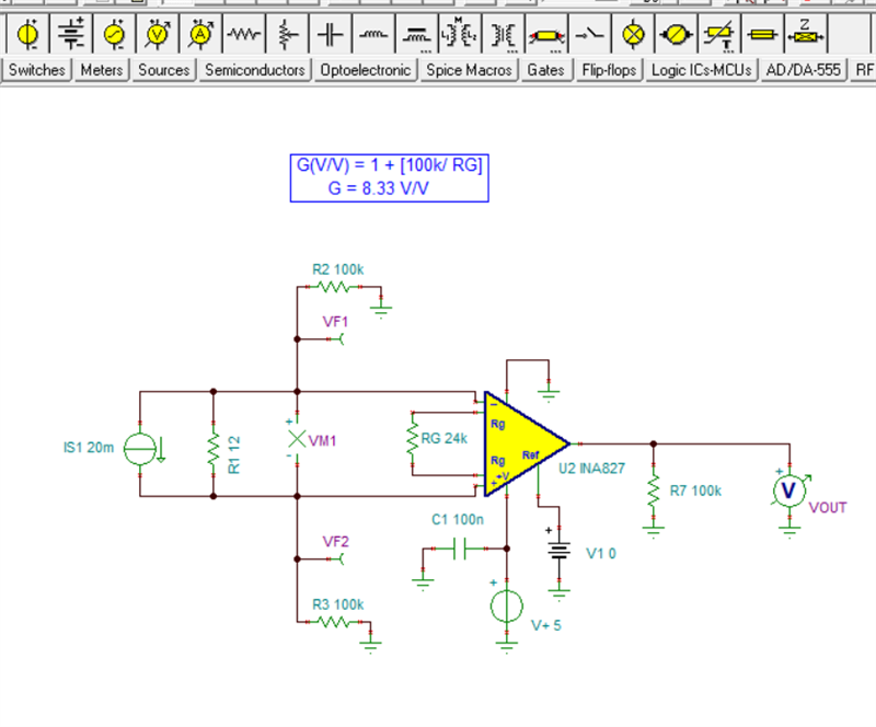
The change made to circuit is instead of internal current source we used External current source 4-20mA and fixed resistor of 12 Ohms instead of RTD sensor

Below is a link to reference design of TI.

 https://www.ti.com/lit/wp/snoa838/snoa838.pdf?ts=1620651177753&ref_url=https%253A%252F%252Fwww.google.com%252F

  • Hi Shwetal,

    your description confuses me. Can you post a schematic?

    Kai

  • Hi Kai

    Thanks for you reply

    Please find attached Schematic link..

  • Hi Shwetal,

    and still using A1 and R8? And where is your signal ground connection?

    Kai

  • Hi Kai,

    This circuit for Constant current source (A1 & R8)  is not used as we are measuring external 4-20mA current in our application

  • The Signal is external 4to 20 mA from another source so Signal Ground is not connected in this circuit

  • Hi Shwetal,

    this will not work because of the input bias currents of A2 and A3. You must provide a path to signal ground for them.

    Kai

  • I tried Adding Resistor R8 2.5K but it did not resolved my issue. can you suggest a better way for signal ground

  • Hi Kai,

    I checked Ib is 18nA max so We added R8 2.5k resistor doing this must resolve the issue with bias current but some How my Gain of Instrumentation amplifier is changed I don't understand reason behind this can you explain

  • How shall R8 help at all? Scream

    Why not doing it this way or similar:

    shwetal_tlv9001.TSC

    Kai

  • Hello Shwetal,

    If you remove A1 and R8 from the circuit, then as Kai points out the input amplifiers lose their input bias current return path. When that happens op amp input will move to whatever voltage levels they must in an attempt to sink/source their input currents. That will almost certainly result in incorrect circuit operation. 

    Including the 2.5 k resistor at R8 establishes a return path for the input bias currents, and circuit operation should be okay. When I run a TINA-TI simulation of the circuit the results are as seen below.

    The concern I have with this solution is the output voltage range that occurs for a 4 to 20 mA input current range. The Vo with a 4 mA Is current is shown to be about 81 mV. The OPA4188 linear output voltage, which is specified in the open-loop gain (Aol) specification is is with an output voltage from (V–) + 500 mV < VO < (V+) – 500 mV, for RL = 10 kΩ. Clearly, 500 mV above ground well exceeds the 81 mV to 418 mV output from the circuit. The input amplifiers U2 , U3  and output amplifier U1, shown below have a 20 k load on their output. This may provide a bit more swing than a 10 k load, but the issue remains.

    Kai's simpler current-to-voltage converter gets away from the output voltage issue; however, the input current is ground referenced.

    Regards, Thomas

    Precision Amplifiers Applications Engineering

    OPA188_4_20mA_02.TSC

  • Thannks Kia,

    I will try this but I am looking for Instrumentation amplifier as Input so that I can switch my circuit to use with 4 Wire RTD and 4-20mA current source with swithc selection.

  • Hello Thomas,

    I tried this circuit and got same result but I have a querie.

    My circuit is not follwing the stadard instrumentation amplifier gain calculation Vo= R2/R1(1+2R5/R6)(Input Voltage Difference)

    In our Case Input Voltage Diffrance is 48mV

    Vo = 10K/10K(1+ (2*10k/3.205k)) * 48mV

    Vo = 7.24 * 48 mV

    Vo = 347.53 mV

  • Hi Shwetal,

    The gain equation you state is correct provided the op amps are operating within their stated linear ranges, and there isn't some other electrical issue with the circuit. Certainly there may be the normal gain error due to resistor inaccuracy, but otherwise the gain should follow the equation. 

    Have you considered using a low-voltage integrated instrumentation amplifier instead of a high-voltage op amp for the instrumentation amplifier function? I propose you have a look at a low-voltage, rail-to-rail input/output (RIRO) instrumentation amplifier such as the INA333. It is well suited for a 5 V supply, and the output range is specified to within 50 mV of the supply rails for a 10 kilohm load. Like any of the op amp circuits it will require input bias current returns.

    The INA333 integrated design includes the precision trimmed resistors that result in much higher performance and accuracy than one can expect from a discrete instrumentation amplifier constructed of individual op amps and resistors. You can program the gain to whatever you need it to be by one RG resistor.

    https://www.ti.com/lit/ds/symlink/ina333.pdf

    Regards, Thomas

    Precision Amplifiers Applications Engineering

  • Hello Thomas

    I tried this circuit simulation in TINA but did not performed as expected and even did not resolved my issue

    can you explain me what went wrong and why?

    INA333 is costlier option for my application can you suggenst me any cost effective option.

    Regards, Shwetal

  • Hi Shwetal,

    Okay, I examined the INA333 circuit closely and there are two subtle errors that prevent the circuit from working correctly. The first is with the return resistor connected off the INA333 +In input tries to force the -In voltage to become negative. That can't happen and besides that the common mode input voltage range of the INA333 becomes violated. The second was my oversight of the fact that the INA333 input common mode voltage on the low end is +100 mV above the negative supply (0 V). Therefore, the inputs can't be referenced to 0 V without using a negative -V supply. The INA333 isn't a good fit for this application.

    I searched our newer instrumentation amplifiers looking for one that has a common-mode input voltage that goes down to 0 V, when -V is also 0 V. The INA827 has a VCM operating input range down to 0 V according to Figure 9, with Vs = + 5 V, and Vref = 0 V. I redid your 4 to 20 mA current sense circuit with the INA827 and the results look encouraging. I decided to use a 100 k input bias current return resistor off each input to better balance the circuit. I believe this circuit should do what you need.

    INA827_Cur_Sense_01.TSC

    Regards, Thomas

    Precision Amplifiers Applications Engineering


  • Hello Thomas

    sorry for delayed reply will try it today 

    Thanks for your reply

    Regards,

    Shwetal