This thread has been locked.

If you have a related question, please click the "Ask a related question" button in the top right corner. The newly created question will be automatically linked to this question.

XTR105: Problem in fixing the Iret

Part Number: XTR105
Other Parts Discussed in Thread: XTR111

Good Morning,

I've developed a sensor (3 electrodes) 4-20mA for chlorine measurement.

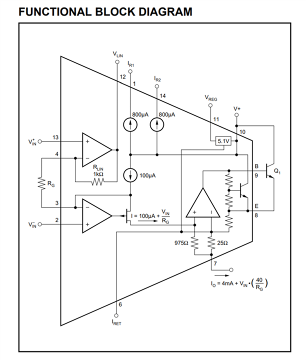
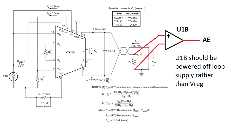
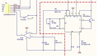
The interface with the external instrumentation is entrusted to XTR105. I'm using the Iret like the "Ground" of my circuit potentiostat. I set the Working Voltage between Counter electrode and reference Electrode through an operation amplifier. In the image the schematic.

if I find continuous currents in the water, the Iret moves and this causing a malfunction of the sensor.
I measured a ddp between the Iret and the GND equal to about 108 mV(in normal condition), in the presence of these currents (depending on the direction of crossing with respect to the sensor) the ddp drops to 56mV or rises up to about 400mV.
How can I block the Iret even in the presence of these currents?

Thanks in advance for your reply!!

Best Regards

  • Hello,

    Without seeing your entire schematic, I’m not sure I understand just how this circuit is intended to work, but I believe there are some problems with the implementation of the IRET and IO pins of the XTR105. The XTR105 is a two-wire transmitter and thus it is important to understand how the “grounding” works.

    The IRET pin is the “ground” return pin for any current sourced from the VREG pin or other current sources. It acts as the “ground” for anything powered by IR1, IR2, VREG, etc. IRET is not a fixed voltage, but rather must float with the loop supply, just as the IO pin floats and changes based on the current consumed. IRET moving when your current changes is not a bug, it’s how the part is intended to work.

    Also, you cannot tie IO to GND. This is the output of the XTR and is not fixed relative to GND, instead moving around based on the current signal to be output. The proper path is from IO, through a load resistance, back to the GND that is associated with the V+ supply of the XTR. The current across the load resistor is your 4-20mA signal, and you can use a difference amplifier or INA to measure across the resistor and get a voltage for use in the rest of your circuit (or just measure single-ended relative to that GND).

    When you use IRET as the VEE supply of the TC913BC amplifier, there is a valid current path between VRG and IRET, so that’s fine in and of itself. However, because the IRET moves around (relative to the main circuit GND), that means the output of the amplifier is also going to move relative to ground. If the circuitry downstream on the “AE” net is not powered on the same VRG supply, then you’re going to have problems because the AE net will be moving relative to ground but nothing else will. You’ll need to implement some kind of isolation scheme here. You might want to consider looking into using a three-wire transmitter such as the XTR111 instead, which greatly simplifies the grounding and eliminates the need for isolation.

    It looks like what you are trying to do is measure the voltage across R7 with the U1B amplifier, but I don’t quite understand your circuit theory. Normally the design procedure would be something like what I mentioned above, you’d use an amp to measure the voltage across the 4-20mA load resistor and then this would be your "AE" signal. Can you share a larger schematic and walk through what you are trying to do?

    In addition, I recommend you check out our TI Precision Labs series on XTRs (https://training.ti.com/ti-precision-labs-amplifiers-introduction-4-20ma-current-loop-transmitters?context=1139747-1139745-1147985-1147753 ). I also recommend this blog series (https://e2e.ti.com/blogs_/archives/b/precisionhub/posts/two-wire-4-20-ma-transmitters-background-and-common-issues ) specifically parts 2 and 3 which discuss loop returns. Part 4 discusses isolation, which you may need to implement at the output of the U1B amplifier. You may find our FAQ helpful as well (https://e2e.ti.com/support/amplifiers-group/amplifiers/f/amplifiers-forum/945188/faq-designing-with-4-20ma-current-loop-transmitters-xtrs-faq-links ).

    Cheers,

    Jon

    Edit: Corrected a typo regarding the IO connection.

  • Hello Jon,

    thanks for your fast feedback!

    I would prefer to send you the full schematic with a more detailed description in private! Can I ask you a private mail? 

    Thank you very much

    Davide

  • Ciao Davide,

    it's very simple: Each current flowing out of the XTR105 via the pins 1, 11, 12, 14 must flow back to the XTR105 via the Iret pin (pin 6).

    See also this thread:

    https://e2e.ti.com/support/amplifiers-group/amplifiers/f/amplifiers-forum/770353/xtr116-incorrect-reference-voltage-and-malfunctioning-4-20ma-output-driver

    Kai

  • Hello Kai,

    Thank you for the answer, but if you look at the schematic, the current you are talking about is the current for my voltage divider (composed by R4 and R7) and the current for the opAmp power supply

    During my measurementit appears that my 4-20 mA measure iis connected to the potential difference between pin 13(V+) and pin 2(V-).

    When I have this current in the water this potential difference does not change ...but the current at the base of my transistor increases and also the 4-20mA signal.

    The feeling I have is that the TC913BC can follow the signal and is not affected by this current which instead annoyng the XTR105UA.

    Davide

  • Davide,

    Kai is not wrong. As stated earlier the IRET pin is the designated return pin for the currents sources from IR1, IR2, VREG, etc. 

    0.8mA from IR1 will be split, some of it going through the off-page circuitry and the rest through the series combination of R4 and R7. 0.8mA through 3.8k ohms would be 3.04V total, or 2.64V across R7. I can only assume the idea of your circuit is to redirect some of that 0.8mA across whatever load spans between Vin+ and Vin-, otherwise you'd just have the same value for "AE" all of the time. 

    Again, however, this is a misapplication of this part. The intention is for the difference between Vin+ and Vin- to be amplified according to the relation IO = 4mA + VIN * (40/Rg), which assuming the R5 potentiometer is set to 1k would mean IO = 4mA + VIN * (40/500) and thus IO = 4mA + 80mA/V * VIN. If VIN is 200mV, this will result in a 20mA output, and if VIN is 0mV, this will result in a 4mA output. This 4-20mA current (your output) passes through the IO pin, and then it should pass through the loop load before completing its path through the loop ground and loop supply. What your U1B amplifier should be doing is measuring the voltage across the loop load, rather than trying to measure the distribution of current within the XTR circuitry. Something like the below.

    I highly recommend you watch this video on how the currents in a 2-wire transmitter work before proceeding further - https://training.ti.com/ti-precision-labs-amplifiers-current-loop-transmitters-basic-design-considerations?context=1139747-1139745-14685-1147755-1147876 

    I am sending you a "friend request" through the forum. Once you accept it, you should be able to communicate with me via direct message. You can share your schematic there or we can trade emails and continue the discussion that way.

    Cheers,

    Jon

  • Hi Davide,

    keep in mind that Vreg can only source up to 1mA. With a too high load at the output of U1B, U1B might draw a too high supply current. This can make the XTR105 go out of control.

    Kai