This thread has been locked.

If you have a related question, please click the "Ask a related question" button in the top right corner. The newly created question will be automatically linked to this question.

LM321LV: Gain-bandwidth Frequency

Part Number: LM321LV
Other Parts Discussed in Thread: TLV9051, OPA2992

Hi Team, 

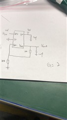
the spec of LM321LV show the Gain-bandwidth Frequency is 1MHz, but in my customer testing circuit the distorted frequency is up to 100KHz. Could you pls help provided any solution to solve it or provided you Gain-bandwidth testing circuit? Thanks!

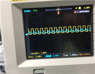
1MHz distorted curve. Yellow input curve, blue output curve.

Testing circuit.

  • Hello,

    There are multiple things going on here. The LM321LV has a small signal bandwidth of 1MHz, this would be for signals less than ~10mVpp. The customer is using a 2Vpp input signal and therefore has a large signal. When using a large signal you will be limited by the full power bandwidth of the device which is dependent on the slew rate of the device. However, full power bandwidth is only for sinewaves, not square waves like the customer is using.

    Using a square wave input (large signal) the output is mainly going to be limited by the slew rate of the device. The output needs to have time to slew to its final value before the input voltage changes. You'll notice in the customer's waveforms that the output begins to rise (on a rising edge input) but doesn't have enough time to reach the final output value before the falling edge of the input signal begins. This is because the device is not fast enough.

    Lastly, the customer is using single supply operation (5V and GND) and has an input signal that goes to 0V (GND). When the input signal is low (GND) the output will saturate to the negative rail (GND) and cause the output voltage to have a delay in responding to the input voltage (from low to high) due to overload recovery time.

    The customer will need to use a much faster slew rate device than the LM321LV and should consider not slamming the output to the negative rail to prevent delays due to overload recovery time. They will need a device with a slew rate greater than 8V/us for the output to rise before the input signal changes. I recommend taking a look at the TLV9051 or for something with a much larger slew rate, the OPA2992. However, the overload recovery time of many devices can be 100's of ns which will require an even faster slew rate since there will be less time for the output to rise to the final value.

    Thank you,

    Tim Claycomb