This thread has been locked.

If you have a related question, please click the "Ask a related question" button in the top right corner. The newly created question will be automatically linked to this question.

INA333: Strain gauge amplifier: zeroing and bridge excitation

Part Number: INA333
Other Parts Discussed in Thread: LM4120, INA848, INA818, ADS1115

Hi team!
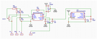
I'm working on an amplifier for strain gauges, it will work with 120ohm strain gauges @5V. Based on this circuit, an ina333 is used to amplify the unbalanced signal of the bridge. It is added 2.5V offset to allow signals belonging from both sides unbalancing. All resistors are 0.05% and 10ppm/°C, because the amplifier needs to work with minimum drift between 20 and 60 °C.
As thread title, my doubts are about bridge excitation: I would like to use 5V precise reference, but I think 50mA are too much to any voltage reference. What can I choose insted?
I know should be better to not zeroing bridge, but INA333 have only +- 0.3 V of differential input, and can be saturated by only initial unbalancing of the bridge. I think the potentiometer in this configuration will drift the same on both sides, leading to common-mode offset will not change the output of INA333.


  • Hi Paride,

    I would like to use 5V precise reference, but I think 50mA are too much to any voltage reference. What can I choose instead?

    We may be able to reduce the current through the Wheatstone bridge sensor, see the image below. There are other options, but this option may be better, since you may also reduced I2R heating within the Wheatstone bridge, though I am not sure the heating may be significant. 

    I am not sure that strain gauge sensor is able to be excited at lower voltage. If not, you may have to make make some adjustment. For instance, reduce R5 and increase R6 series resistors. 

    There are other options, but no excitation voltage is as precise as the reference voltage. You may also buffer the 5Vref with a precision op amp to increase 5Vref's sourcing current. You need to find an op amp that is capable to source up to 50mA current. If this is the option you want to go, please let me know. 

    I know should be better to not zeroing bridge, but INA333 have only +- 0.3 V of differential input, and can be saturated by only initial unbalancing of the bridge.

    Please see the following thread where Kai talks about balancing a sensor bridge. 

    https://e2e.ti.com/support/amplifiers-group/amplifiers/f/amplifiers-forum/975733/ina125-what-is-the-recommended-way-for-balancing-or-zeroing-inputs-from-a-strain-gauge-wheatstone-bridge-into-or-through-an-ina125-or-similar/3606322?tisearch=e2e-sitesearch&keymatch=zero%252525252520out%252525252520bridge%252525252520sensor#3606322

    Other option is doing both balancing the bridge and zero out the output of INA333 circuit. (or calibrate  For sensitive strain gauge measurement, stain gauge calibration is necessary to calibrate out the unwanted errors, such as temperature, INA333's Vos, bridge slight imbalance, humidity etc. You may perform two  point strain gauge calibration to make sure the sensor is performing within a specification. You may then check a known force against the sensor after a system calibration, if accuracy measurement needs to be ensured.  

    INA333 Strain Gauge 08052021.TSC

    If you have additional questions, please let me know. 

    Best,

    Raymond

    .

  • Thank you Raymond,
    BALANCE ISSUE
    I already read the topic you linked. Unfortunatly, I have to work with already-installed strain gauges and that could result in big differences between 2 strain gauge resistence. I can't calibrate if on zero position there are 5mV, because INA333 is already saturated.
    I know the best option will be to have an external shunt fixed resistor, but it requires a full kit of precision resistors and a lot of patience. What do you think about the drawn solution?

    EXCITATION ISSUE
    Speacking about excitation, I think the solution with series resistors will reduce not only the current but also excitation voltage across the bridge: if I'm not wrong, referring to your image  only 1/5 of Vexct is applied on the bridge.
    The sensibility of my sistem is 0.38 mV/V on maximum load (delta resistence on the gauge about 0.19 ohm).
    The output of amplifier using 1V across the bridge should be 2.88 V on maximum load (considering 2.5V output on balanced bridge), seems low.

    The buffering solution is intresting, could it bring errors due to temperature changement?

    Thank you again

  • Hi Paride,

    datasheet of LM4120 shows how to boost the output current. Additionally (or alternatively !), you could carry out a ratiometric measurement by taking the 5V bridge excitation voltage as reference voltage for the ADC. Another idea is to read the 5V bridge excitation voltage by a free ADC channel and carry out a pseudo ratiometric measurement.

    For ultra low temperature drift, offset voltage trimming by the help of a cermet trimmer should be avoided. This would destroy the balance of temperature coefficients of strain gauges, because strain gauges and cermet trimmers show different temperature coefficients.

    It's hard to get ultra-low drift performance with an improper set of strain gauges showing a high initial offset voltage. If there's absolutely no way to omit the cermet trimmers, a software based temperature drift compensation by the help of a NTC could be performed. But then you would need to put every single bridge into the oven and run an individual temperature compensation.

    Kai

  • Hi Paride,

    The sensibility of my system is 0.38 mV/V on maximum load 

    Yes, the application will need to maximize excitation voltage in order maximize the overall change, which is approx. 1.9mV or 0.1815Ω in delta of the load cell. 

    In this case, I probably will not use potentiometer as Kai pointed out. You may use the potentiometer or resistor box to check out the required value and replace with the balanced circuit with a fixed resistor or balance the Wheatstone bridge circuit directly by hand without potentiometer. It will take more time, but you do not need to worry about thermal drift over temperature in potentiometer (you may place a calculated resistor value on top of 120Ω (piggyback) to null out the circuit after checking out the balance of an Wheatstone bridge).  

    Typically, the type of sensitive measurement are done in a controlled temperature environment or indoor. If the ambient temperature is changed at the minimum, potentiometer may be acceptable.  Personally, I do not use potentiometer in a precision circuitry. 

    With such small signal change, I will suggest a different instrumentation amplifier, such as latest INA848 or INA818, since you need high gain. INA848 is a fixed gain instrumentation amplifier with very high CMRR specification. If the analyzer is not for portable or battery operated application,  INA848 or INA818 will be a better option. INA333 will be good for low power and portable strain gauge application. 

    Here is ratiometric example implemented in 3-wire RTD measurement application. 

     https://static5.arrow.com/pdfs/2013/11/24/3/19/23/744/txn_/manual/slau520.pdf

    If you have additional questions, please let us know. 

    Best,

    Raymond

  • Thank you both, I will try to reply per points:

    Amplifier selection
    INA333 was selected due to low temp drift (better than INA818) and because of this example provided by TI. I think 1000 gain is enought, it allows to almost all 5V range (2.5V is the ideal output in zero load condition, -+1.9 V belonging from 1.9mV amplified 1000 times)

    Bridge zeroing

    Following your suggestions, a pad will be prepared on the PCB to sold low-drift resistor in parallel to one arm of the bridge

    Bridge excitation and adc

    I think the best option will be to use a ratiometric or pseudo ratiometric mesurement.
    At first instance I didn't care about adc because the plan was to just amplify the strain gauge to be aquired in external sistem.
    Considering that probably there will be 12 strain gauge to acquire, could be an idea to use ADS1115 analog-digital converter and arduino-based datalogger to store data?
    ADS1115 is selected because of his easy set up and good documentation in arduino word.

    Thanks again

  • Hi Paride,

    Regarding to resistors used in Wheatstone bride. 

    Low thermal drift resistors will definitely reduce error measurement. I do not know what strain gauge's thermal drift specification is. If you are able to select resistors with similar thermal coefficient, then this will be the best options. 

    If same or similar temperature coefficient (PTC or NTC or Low drift etc.) resistors are used in Wheatstone bridge, measured signal changes in strain gauge will be insensitive to changes in temperature environment, since the thermal drift or changes will be in synch or similar to ratiometric measurement. 

    I think that you have a good understanding in how to meet your design requirements. If you need additional help, please let us know. 

    Best,

    Raymond