This thread has been locked.
If you have a related question, please click the "Ask a related question" button in the top right corner. The newly created question will be automatically linked to this question.
Hi teams,
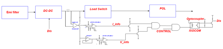
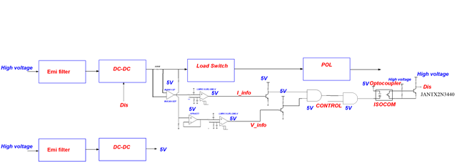
My customer wants to use LM193QML-SP to detect current (INA901-SP/INA240-SEP) and voltage (OPA4277),
and he is wondering how to deal with the Vref which in the block diagram as below.
Please give any comments or advice on this block diagram, thanks.
Ryan
Thanks for your post but unfortunately I cannot see the details of the reference voltage you are eluding to. Please specify the operating voltage of the comparator and the value of the reference. Understood that this is only a simplified block diagram, but please make sure they include pullup resistors when implementing.
Chuck
Sorry Ryan but I am still not able to provide much guidance. I understand that the operational voltage of the comparator is 5V but can you comment on what the reference voltage is? One channel is voltage sensing and the other is current sensing which seems like a good use case but your question is specific about the reference. What about the reference is your question? Are you asking how to create the reference or what range it can be?
Chuck
Sorry for not describing the problem clearly.
Yes, I'm asking how to create the reference or what range it can be?
Thanks for your patience.
Hi Ryan,
I guess the disabling is for turning-off the DC/DC modul in the case of overvoltage and overcurrent? This would mean that 5V will arrive at the +input of lower LM193? But this will not work with a LM193 being supplied with 5V supply voltage, because the common mode input voltage range is only up to Vcc-2V = 5V-2V = 3V. So the LM193 would need to see a higher supply voltage than 5V or you would need to mount a voltage divider at the +input of LM193.
Ka
Kai
Maybe I am not quite following your point, but I am thinking we still may be ok with this idea as long as we have an external reference that is derived from the 5V source that is within the common mode range you described. This could be a simple resistor divider of the 5V source which I assume is regulated and not dependent on the DC/DC converter that will get disabled. As long as one of the pins is in the recommended common mode range, the output of the comparator will be in the correct state.
Chuck