This thread has been locked.

If you have a related question, please click the "Ask a related question" button in the top right corner. The newly created question will be automatically linked to this question.

OPA4202: Value of bypass capacitors

Part Number: OPA4202

Hello,

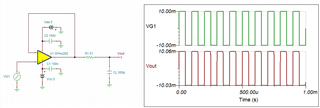
I am designing amplifier circuit used OPA4202.

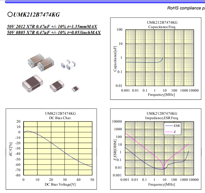
The data sheet of OPAx202 recommends the value of 0.1uF bypass capacitor for each power input terminal of OPAx202.

(Section 9: Power supply recommendations)

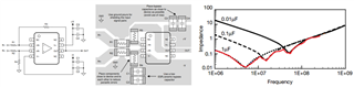
Also figure 49 of OPAx202 datasheet shows 4 bypass capacitor (C1, C2, C3, C4) for V+ terminal and V- terminal.

I will use OPA4202 on frequency of DC to 10kHz.

I would like to confirm suggested value of bypass capacitors.

Regards,

MESH

  • Hi Mesh,

    I don't see figure 49 in the latest datasheet.

    100nF decoupling caps is the standard for a standard application. If you drive heavy loads or heavy capacitive loads, on the other hand, I would eventually increase the decoupling capacitance. This depends a bit on the quality of supply voltage regulation and on how much the OPA4202 is distanced from the regulators.

    Can you tell more about your application?

    Kai

  • Hi Mesh,

    I will use OPA4202 on frequency of DC to 10kHz. I would like to confirm suggested value of bypass capacitors.

    It seems that your operating frequency range is from DC to 10kHz. Typically, we use 100nf coupling capacitor for the application. If your power supply is noisy, you may place multiple coupling capacitors in parallel. A standard practice is to select the bypass capacitor in a decade apart. You may also use different size of capacitors in combination with the multiple coupler method. Smaller size will have lower ESL, so its impedance will rise slower with increasing in frequency. 

    The reasons behind the practices are: First, you want to have multiple low ESR coupling (bypass) capacitors that can filter out unwanted high frequency signals for a noise sensitive application. If op amp's power rails consist of high frequency noises, you want re-direct high frequency signal to ground via low ESR capacitor. Capacitor's spice model consists of ESR + Xc + X_L, and the impedance vs. frequency responses are shown in the impedance plot above.

    At higher frequency, capacitor behaves like a short. The voltage ripple is created across ESR*Iac that goes through the capacitor. Lower ESR in capacitor, lower the ripple voltage will develop across an op amp's supply rail.  At the op amp's supply rail, power rail prefers to have DC_amplitude + low_ripple_AC_voltage. By implementing multiple bypass capacitors, it may be able to broaden low ESR specification over a frequency range, hence you may remove wider range of unwanted frequency that may couple into op amp's internal circuit (if the application's power supply is noisy, e.g. switching power supply). 

    This is just one aspect of the use of multiple bypass capacitors. As Kai pointed out, there are other factors when implementing different values of coupling capacitors. It also depends on the type of application. For OPA4202 operating from DC to 10kHz application, 1uf and 0.1uf low ESR capacitors may be adequate for the application.   

    If the low noise design is required in an application, you also need to check the datasheet of low ESR capacitors used in a design, and make sure that it will perform well over frequency, temperature and load requirements etc.. 

    If you have additional questions, please let us know.

    Best,

    Raymond 

  • Hi Kai klaas69,

    Thank you for your reply.

    I will use OPA4202 for cable drive of 1m to 2m.

    MESH

  • Hi Raymond,

    Thank you for your reply.

    I will add 100nF capacitor and check the operation. 

    MESH

  • Hi Mesh,

    I will use OPA4202 for cable drive of 1m to 2m.

    OPA4202's driving output  with 1m to 2m seems long for the application. What type of load are you driving at the end of the long cable?

    If OPA4202 is driving capacitive load, the op amp may get unstable, which it has nothing to do with coupling or bypass capacitors. When op amp is unable, the output will start to oscillate under certain conditions. If this is the case, the op amp is required to be compensated.

    You are only operating from DC-10kHz range, you may be ok, but I will check it to be sure. You may check the stability of the op amp by applying a small step function at input, say 0-100mV or less, and check the output response at the load. If the output duplicates the input signal without ringing, you are good to go. 

    If the output is shown ringing per the above test, I can attempt to compensate the circuit for you. 

    Best,

    Raymond. 

  • Hi Raymond,

    Thank for your reply.

    I am considering of connecting an amplifier circuit (high impedance input) in another component to the end of a long cable.

    I assume the capacitance of the cable is approximatery 200pF/m.

    I am considering the circuit with reference to Figure 40 and Table 2 in Section 7.3.1 of the data sheet, and I intend to set RISO = 51ohm with gain = +1.

    Please let me know if you have any advice on the stability of OPA4202 for this circuit form.

    Based on your advised in the previous reply, I plan to carefully check the presence or absence of oscillation at the circuit operation check.

    Regards,

    MESH

  • Hi Mesh,

    The setup should be stable. It has enough phase margin of  88 degree, which it more than enough. Riso of 51Ω will contribute and maintain an adequate phase margin even capacitive load is increased up to 10nf in the configuration. 

    OPA202 Step Transient 08202021.TSC

    If you have additional questions, please let us know.

    Best,

    Raymond

  • Hi Mesh,

    with a 200pF load capacitance a simple 100...470n X7R/0805 decoupling cap (per supply voltage) should do. Something like this:

    The capacitance loss at +15V supply voltage is only 10%.

    Kai

  • Hi Raymond,

    Thank you for your reply.

    Your reply is very helpful for me.

    Regards,

    MESH

  • Hi Kai,

    Thank you for your reply.

    I will check 100nF to 470nF capacitors.

    Regards,

    MESH