This thread has been locked.
If you have a related question, please click the "Ask a related question" button in the top right corner. The newly created question will be automatically linked to this question.
Dear sir,
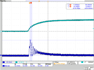
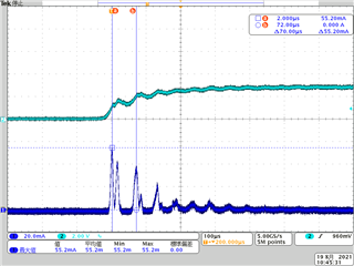
We would like to confirm if exceed 8mA or not.
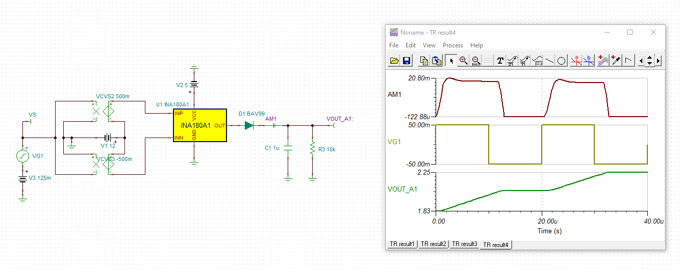
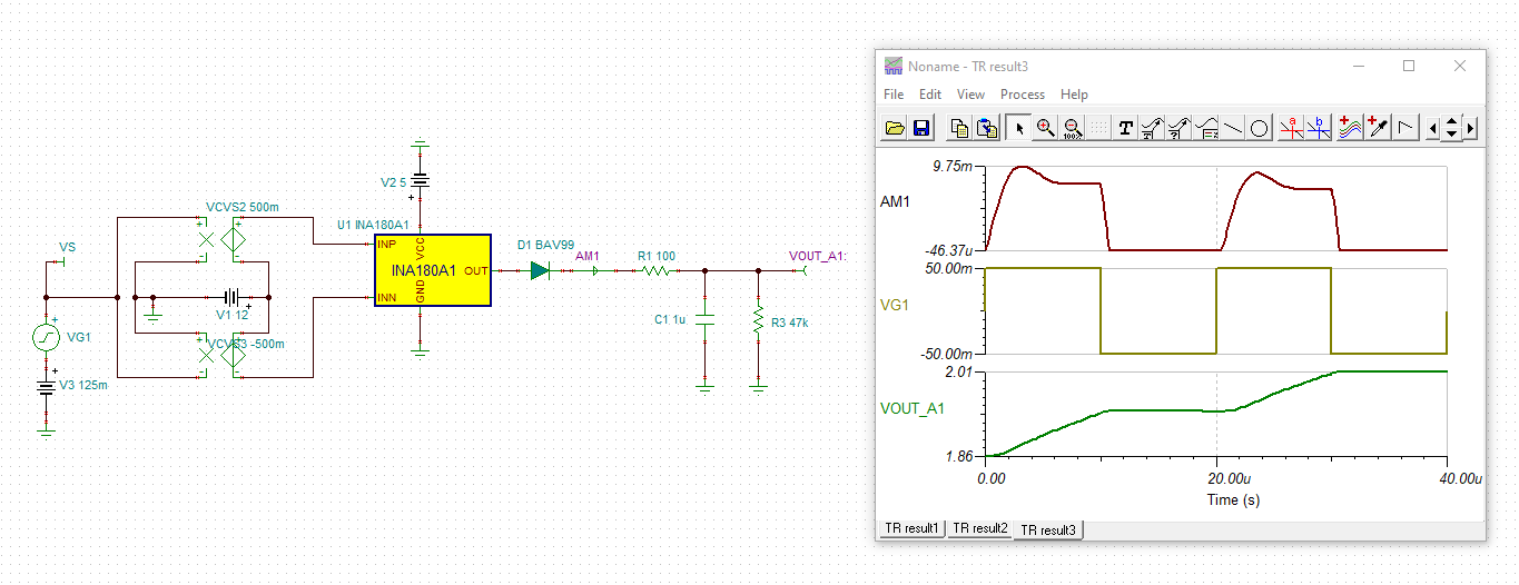
We will connect the capacitor to the INA output.
For specification of Absolute Maximum Ratings, Maximum current output is 8mA
But for figure 19, typical characteristics is over 8mA.
Thanks & best regards,
Hi,
At least under DC condition, the device shouldn’t be able to source 48mA (sinking yes). However it is possible that for a brief moment in-rush current that large can get through. Can you please zoom in on the pulse and see what it looks like?
The other possibility is that measurement artifact makes the pulse look bigger than it actually is.
The part is capable of delivering more than 8mA DC. However this spec is to protect the metal trace’s long term reliability under sustained large (>8mA) current. For short pulses, this restriction can be relaxed.
When not sure, a current limiting resistor should help reduce the current.
Regards, Guang
Dear Guang,
Thank you for your reply.
Well, noted.
Blue line wave is output current.
Peak current is 58mA.
But pulse width is very narrow(16us or less).
Would you please confirm to effect device damages.
Thanks & best regards,
K. Yamada
Hi Kenta,
keep in mind that the uncharged 1µF cap at the output of INA180 looks like a short-circuit and you force the INA180 to charge-up the 1µF cap with the short-circuit current. You can also see that the internal short-circuit protection sets in. You heavily overstress the INA180 by this . Such a situation should be the absolute exception which may occur one time a week or so, but not perdiodically during standard operation.
As Guang already mentioned you should add a current limting resistor:
This will also prevent instability caused by the huge capacitive load.
Kai
Hi Kenta,
Thank you for the additional scope plots. These pulses are short. Also they are grouped far from each other based on previous figures (low duty cycle). The situation is not we would consider as risky, it should be OK to use as is, or you could include a small limiting resistor.
Thank you Kai for the great simulation demonstration.
Regards, Guang
Dear Guang,
thank you for your cooperation.
Well noted, thanks!
I will consider to add small limiting resistor.
Best regards,
K. Yamada
Dear Kai,
Good day.
Thank you for your advice.
Well, noted.
I will consider to add small limiting resistor.
Thanks & best regards,
K. Yamada