Hello ,
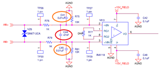
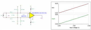
We are currently using the said part for sensing wide range of voltage , please find the schematic in pdf & its LTspice equivalent ( just for pictorial representation of single channel ) .
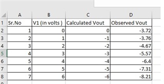
Problem statement : we have design the said circuit for gain =1 . However some strange pattern( offset ) is been observed on all the INA ( we are using 7 such INA in the design ) . Please find reading for single channel .
The offset appears to be consistent in all INA .
Can you please comment on the same .
Gaurav 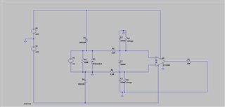 4263.pdf