This thread has been locked.

If you have a related question, please click the "Ask a related question" button in the top right corner. The newly created question will be automatically linked to this question.

OPA4171: Effect of capacitor in feedback loop-OPA4171

Part Number: OPA4171
Other Parts Discussed in Thread: TINA-TI, OPA171

Hi,

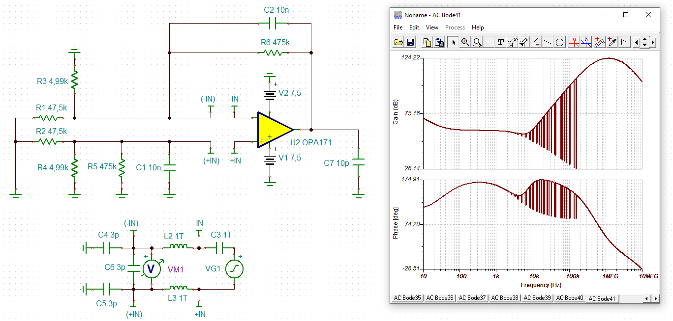
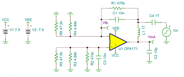
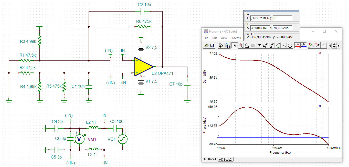
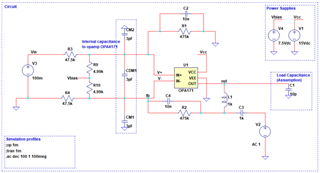
I have below circuit as a difference amplifier with the gain of 10. The circuit has feedback capacitor of 10pF. This is more like differential to single stage configuration and around 7.5V DC offset is provided at the input.

I have following questions:

1.  I am using the break the loop method (feedback loop) to understand the frequency response of the circuit. And added input capacitances to the simulation from datasheet of OPA4171.

As per one reference note: feedback capacitor > CCM + CDIFF,  which is true in this case. I want to understand the role of feedback capacitor.

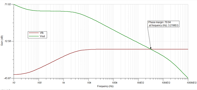
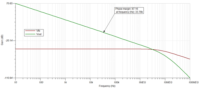
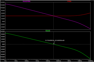
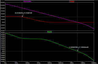
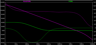
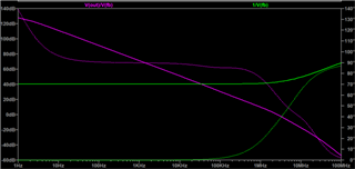
2. I have attached frequency response graphs with and with out feedback capacitor. It is said that to neutralize the affect oh phase due to input capacitors, I am not understanding what are advantages in terms of phase and gain.

3. Does this feedback cap will make RC filter with the feedback capacitor, in this case 33Hz cut off as (10nF and 475k). And is this adding a pole at 33Hz in the feedback loop curve?

4. Also is this the right way to deploy feedback loop break method in case of difference amplifier?

Please help me to understand above queries

Simulation with feedback capacitor

Simulation with out feedback capacitor

Regards,

Sunney

  • Hi Sunney,

    unfortunately, I don't get the TINA-TI simulation to run. I guess there's something wrong with the model? Or it has to do with the fact that I run the TI's reference design?

    sunney_opa171.TSC

    Kai

  • Hi Sunney,

    Before I get to answering your questions I just want to let you know that the input capacitance is actually built into the model for the OPA171! 

    Your simulation circuit was close but not quite right on how to properly break the circuit. Any signal source, other than the one that's used for the open loop analysis should become ground. I also recommend using a 1TH inductor and 1TF capacitor to be safe. I recommend taking a look at the TI Precision Labs learning material located here. It goes into far more details on how to simulate stability! 

    The results with the feedback capacitor:

    The results without the feedback capacitor:

    Let me know if you have any other questions! 

    Best Regards,

    Robert Clifton 

  • Hi Robert,

    Thanks for correcting my mistake, I am getting similar results as yours after updating the break-the-loop method.

    Also I noticed that you have given dual power supply where as I was using only Vcc and gnd. I think you have done this since we are doing AC analysis. Is that right? I have seen the video link (You have shared) and all the example circuits are having dual power supplies.

    without capacitor

    loop gain (Vout) = 33.7KHz (where loop is closed)

    with capacitor

    Adding a pole at ~33Khz in the feedback path (1/Vfb curve) so that the fc can be increased to 3MHz?

    How does it help?

    Regards,
    Sunney

  • Hi Sunney, 

    You are correct! When doing AC analysis, it's easier to put the op-amp in dual supplies and make the common mode voltage 0V. The easier you make it the less likely you make a mistake after all! 

    Don't forget that the phase margin is still important to the overall stability of the system!  Don't let it get to low or your op-amp could oscillate! 

    Best Regards,

    Robert Clifton 

  • Hi Robert,

    can you please post your TSC-file?

    Kai

  • Hi Robert,

    Few clarifications on break the loop method:

    Loop gain (Red trace) should be 20db as there is 10V/V gain, not sure why it is showing 40db.

    Reducing the loop gain to 0db after adding a pole at 33Hz means the overall frequency response of circuit is reduced to pole frequency of 33Hz?

    Yes, phase margin is important for overall stability and in this case it is reducing to ~79 deg from ~87deg, however that should be fine as it is > 45 degs

    Regards,

    Sunney

  • Hey Sunney and & Kai, 

    Robert is OOO today on Holiday. I unfortunately do not have access to his TSC file but he will post it tomorrow when he is back. Sunney, I agree that 79 degree is still enough phase margin. 

    All the best,
    Carolina

  • unfortunately, I don't get the TINA-TI simulation to run. I guess there's something wrong with the model? Or it has to do with the fact that I run the TI's reference design?

    Kai, I also get noise often when doing both inputs. Greatly reducing the 1T values to 100 is clean except for one noise glitch. Changing C3 relative to L2,L3 can move where this single glitch happens. The glitch doesn't seem to change the results except for the frequency range near the glitch.

  • Hi Ron,

    cool, this really does the trick!

    Thank you Relaxed

    Kai

  • Hi Sunny and Kai,

    Sorry for the delay! Here's the TSC file: OPA4117 Effect of capacitor in feedback loop OPA4171.TSC

    The reason for the 40dB gain is from the paralleled 47.5k with the 4.99k. If you remove the 4.99k then you will see the output become 20dB. 

    With careful implementation of the 33k pole, it could. There's several factors on how it's implemented and how much it interreacts with the rest of the system.

    Best Regards,

    Robert Clifton