Other Parts Discussed in Thread: LM4030, INA333, OPA333, XTR106, REF3312, OPA187, INA118, INA818
Hi--
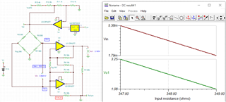
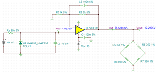
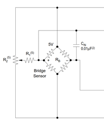
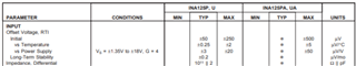
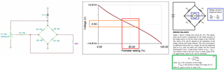
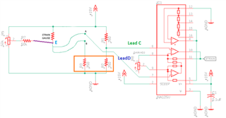
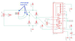
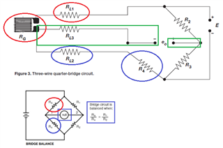
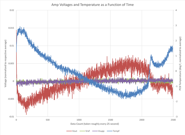
I'm using a 350ohm strain gauge to approximate a load applied to a cantilevered beam. I sloppily prototyped this circuit on a breadboard using an INA125P and received suitable results. However, when running this on a proper PCB with the INA125U (and 0.01% 350ohm resistors in the wheatstone bridge), I'm getting substantial noise on the output.
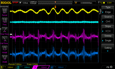
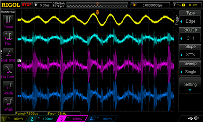
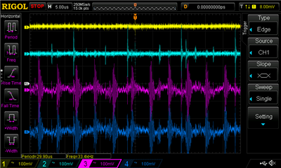
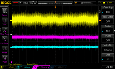
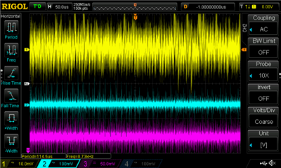
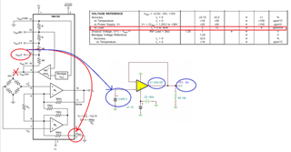
One thing I noticed is that the 2.5V reference has quite a bit more noise on the INA125U than the INA125P--about 230mVPP vs 20mvPP (as measured on oscilloscope).
Here's the difference between my prototype and "final" setups:
| Parameter | Prototype | "Final" |
| Power supply | 24VDC wall wart | 5VDC rectified output |
| bridge resistors | 1% wire wound 350ohm | 0.01% 350ohm SMT |
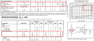
| Amplifier | INA125P | INA125U |
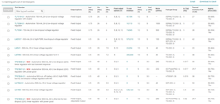
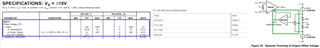
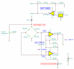
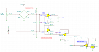
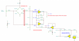
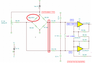
Both designs use the 2.5V voltage reference, and are operated in single supply mode. Here's my schematic:
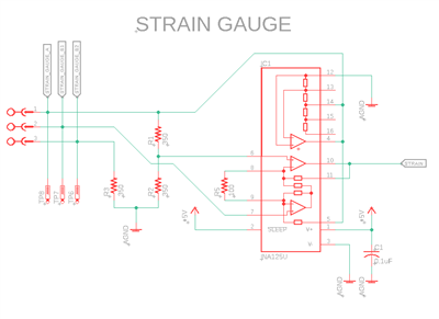
Can you advise on any ideas why I'm getting so much noise from the reference output? Do you see any issues with my schematic? Would you recommend a different amplifier for this application?
Thanks!
Sandheep