This thread has been locked.

If you have a related question, please click the "Ask a related question" button in the top right corner. The newly created question will be automatically linked to this question.

PGA308: The capacitor connected to VIN1 and VIN2

Part Number: PGA308
Other Parts Discussed in Thread: TINA-TI

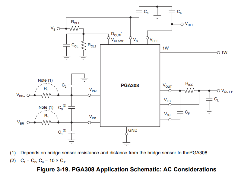
Section 3.10 of the user's guide describes the capacitors connected to VIN1 and VIN2.

I have a question about the following.

・It is stated that the source resistance is 10kΩ or more, but where does the source resistance refer to?

・The following is a description of capacitor capacitance, but does the capacitance of C3 need to be 1~2nF?

 C1 = C2, C3 = 10 × C1

 For example, would there be a problem if C1=C2=1nF and C3 = 10×C1 = 10nF?

Best Regards,

  • HI,

    There is flexibility in selecting the corner frequency of the input filter at the PGA308 inputs.  In general, the corner frequency of the filter is selected according to the bandwidth requirements specific to the sensor application and the noise filtering requirements of the system.

    The PGA308 User Guide recommends use a low pass differential and common-mode filter with the capacitor ratio of C1=C2 and C3 = 10xC1.  Using the 10x ratio for the differential capacitor against 1x to the common-mode capacitors tends to offer good common-mode and differential noise rejection results; and tends to be less sensitive to the tolerance variation/mismatch of the capacitors used on the filter.  Therefore, it is often recommended to use a C3 capacitor to be ten times larger than C1,C2 to attenuate any common-mode signals that become differential as a result of the mismatch in C1 and C2 on instrumentation amplifier applications. See below.

    To answer your question, using a  C3=10nF; and C1,C2=1nF is optimal.

    Thank you and Regards,

    Luis


  • Thank you for your answer.

    Does this mean that I can freely set the capacitance of the capacitor as long as it is designed as follows?

    C1 =C2, C3 = 10 × C1

    Are R1 and R2 resistors to be designed according to the effect of noise and combined with C1 and C2 to form a low-pass filter?

    Best Regards,

  • Hi User,

    This filter is at the PGA308 instrumentation amplifier input and therefore there is flexibility when choosing the capacitor values.  In general, the corner frequency of the filter is chosen to support the bandwidth requirements of your application.

    When using a 10x differential capacitor and 1x common-mode capacitor ratio, the corner frequency is primarily defined by the differential capacitor, where the 10x differential capacitor dominates over the common-mode capacitors.  An approximate equation can be used to determine the corner frequency when using 10x CDIFF and 1x CCM1,2 capacitors:

    There is flexibility when choosing the resistors.  Designers often use resistors in the ~10s of kΩ range.  Using resistors in this range provides some level of protection to the PGA308 inputs for inadvertent circuit miswiring, limiting input current to the sensitive inputs during a fault condition. For example, using a 10x differential capacitor of CDIFF=100nF and 2 common-mode capacitors of CCM1,2=10nF with R1=R2=39.2kΩ resistors will provide a differential signal corner frequency of about ~19.22Hz (or about ~20Hz using the approximate equation/calculation above):

    TINA-TI SPICE simulation file:

    Input_filter.TSC

    Thank you and Regards,

    Luis

  • Thank you for your answer.

    I found out that the capacitor values can be selected flexibly and that the simulation can be done with the approximate equation and SPICE model you gave me.

    Is the approximation formula you gave me available in some application note?

    Best Regards,

  • HI User,

    Please find attached "The Instrumentation Amplifier Handbook", by Neil P. Albaugh from the Burr-Brown days a few years back.  The handbook discusses several topics related to instrumentation amplifiers that are quite useful today.

    On the section, "Noise Filtering the IA Input the Wrong Way—Making A Bad Situation Worse", on p.48-53 discusses the effects of capacitor/resistor mismatch on the common-mode filters, and discusses using the 10x CDIFF and 1x CCM1,2 capacitor ratio, where the filter with the 10x differential capacitor is much less sensitive to these capacitor mismatch.

    Burr-Brown The Instrumentation Amplifier Handbook.pdf

    Thank you and Regards,

    Luis

  • Thank you for your response and the materials you provided.

    My question was answered.

    Thank you for your support.