This thread has been locked.

If you have a related question, please click the "Ask a related question" button in the top right corner. The newly created question will be automatically linked to this question.

INA849: INA849 single supply for high side AC current measurement

Part Number: INA849

Hi,

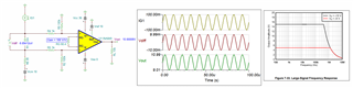
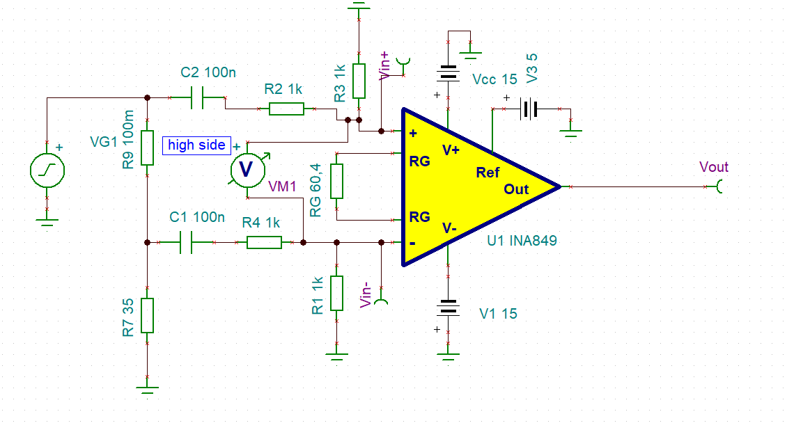
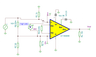
I'd like to build a high side current measurement in the frequency range of 100kHz to approx 6 MHz, using the INA849.

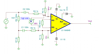
It works just fine with a supply of +/-15V. How would I have to change the circuit in order to use a single supply of +36V?

  • Hi Stefan,

    If I understood the Vcm of 10V correctly that is implied from analog engineer's calculator, below is AC current measurement simulation. 

    Please be aware of the large signal BW limitation in INA849 as shown in figure 7-33 , see the captured image above.

    I removed the 1kΩ voltage divider in the INA849 and replaced with 100kΩ or larger (or you may also remove 100kΩ entirely). The voltage divider in front of IAs may result unwanted differential input errors, unless the voltage divider is perfectly matched. If you want to attenuate the input signal, you may reduce the Rsense resistor from 100mΩ to 50mΩ or reduce the INA849's gain from 100 to 50V/V.  

    Enclose is the Tina simulation. 

     INA849 6MHz 11172021.TSC

    If you have additional questions, please let us know. 

    Best,

    Raymond

  • Hi Raymond,

    Thanks for the quick answer!


    I think the information that was missing in my first post was the excitation that comes from an amplifier that is resembled by the voltage source VG1.

    The signal from the amplifier has 20Vp-p and 20Vdc. So I guess my Vcm is rather approx 20V right?

    So I tried the approach you suggested, but unfortunately with limited success:

    I tried to account for the limited large signal response at high frequencies by limiting the amplification (thanks for the hint!). But my Vout is highly distorted.

    I left the 1k resistors there as the datasheet suggests them for an input bias return path. Am I misunderstanding that section in the datasheet?


    Thanks for your support! 

    Regards,

    Stefan

  • Hi Stefan,

    I was not clear what the previous circuit is intended to do. 

    Below is the current simulation. Please watch for the Vcm mode. Vcm in DC is 20V, but the (DC Vcm) + input swing exceeds 36Vdc or supply rail. The Vcm range is captured in the image below. 

    Enclosed is the simulation. 

    INA849 6MHz 11182021.TSC

    Regarding to input bias return path, the input has a path to ground, so it is ok as is. If the input is floating, then you will require to provide a path to ground as demonstrated in the image capture above. 

    If you have other questions, please let me know. 

    Best,

    Raymond

  • Hi Stefan,

    I hope that your issues have been resolved. I am going to close this inquiry. If you have additional question, you may re-open the thread or create a new one via E2E forum. 

    Best,

    Raymond

  • Hi Raymond, 

    Thank you for your enlightening clarifications!

    How realistic is an attenuation in order to fit into the specified Vcm range of the amplifier?

    Can it be done with good smd resistors or does it have to be a laser trimmed resistor network in one package like the lt5400? Does TI have an attenuator or resistor network or anything that would be fit for the purpose?

    Kind regards,

    Stefan 

  • Hi Stefan,

    Can it be done with good smd resistors or does it have to be a laser trimmed resistor network in one package like the lt5400?

    Yes, you have to use precision trimmed resistor network in order to maintain the high CMRR in INA849 part. At the moment, we do not have discrete matching resistor package as you indicated. TI integrated these matching resistor network in difference amplifiers. Enclosed is a reference of E2E discussion about the topic

    https://e2e.ti.com/blogs_/archives/b/thesignal/posts/difference-amplifiers-the-need-for-well-matched-resistors

    I would recommend to use difference amplifier to attenuate your input sensing voltage. You may also use our current shunt monitor to accomplish the same task. Or if you are able to move the current shunt to a location that is between high and low side of the powerline, where Vcm is operating in the range of INA849 part. 

    Below are the suggestions of high Vcm of difference amplifier, say INA592 INA149 INA597 etc.. We have series of difference amplifier for various applications and you may find it in the link below. 

    https://www.ti.com/amplifier-circuit/difference/products.html#p4min=80;90

    The links below are the current shunt monitor integrated in the difference amplifiers. 

    https://www.ti.com/amplifier-circuit/current-sense/products.html#p2192=Integrated%20Shunt

    https://www.ti.com/amplifier-circuit/current-sense/power-current-monitors/products.html#p726max=40;48&sort=p726max;desc

    If you have additional questions, please let us know. 

    Best,

    Raymond