This thread has been locked.

If you have a related question, please click the "Ask a related question" button in the top right corner. The newly created question will be automatically linked to this question.

Current consumption of the LF356M

Other Parts Discussed in Thread: LM318, TL071H, TL081H, LF356

Hello,

we got a very very mature design were the current consumption of the device is critical.

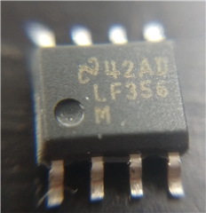
Older Devices we got in our lab stock are marked with 42AD and got a dent near Pin 1

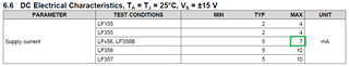
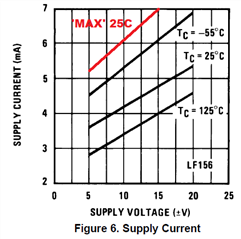
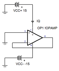
All of that devices show a current consumption of about 3.5 mA at no load +/- 5 V supply.

Our manufacturer got devices wich are marked with 8C2N with no detent but a laser marking for pin 1.

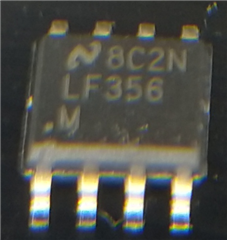
All of that devices show a current consumption of about 5.5 mA at no load +/- 5 V supply.

Theese devices seems also to be a little bit faster than the older ones.

The +2mA current causes troubles in our circuit, which should not to be changed.

As i found no PCN were a change of the circuit was mentioned i am wondering if that behaviour is just bad luck, or a counterfeit  or if there was a change of the product in the past ?

  • The 3.5 mA value is consistent with figure 6 in the datasheet. And even a redesign would not change power consumption and speed by that amount.

    5 mA sounds as if it could be something like the LM318. Can you check if there are clamping diodes between the inputs?

    Did you buy them from an authorized TI distributor? If not, try getting fresh devices from www.ti.com/store/ti/en/p/product/?p=LF356MX/NOPB.

    If you want to reduce consumption, consider the TL071H/TL081H (which are CMOS devices).

  • Thank you Clemens for your fast response.

    I dont know from which channels the LF356 were sourrced by our manufacturer.

    I measured the input pins of both devices:

    Our old one (with the detent) shows no clamping, the newer ones (without detent) shows 1.3 V/ 0.7V clamping voltage.

    I will ask from which source the LF356 were bought..

    Best regards

  • The LF356 does not have clamping diodes. These devices definitely are fake.

  • Is TI selling fake devices ?

    Our supplier just sent me the delivery note from TI.... [note deleted]

  • Hello Spoerl,

    I did a quick check and same die has been used for at least the last 9 years. I also checked symbolization and instructions say pin 1 notch. A printed dot is not a notch assuming words mean anything. If a part can be fake, so can a note also be. Unfortunately, I can't determine or declare the legitimacy of the samples.

    Please follow this link : 

    https://www.ti.com/support-quality/quality-policies-procedures/anti-counterfeit.html

  • Hello Ron,

    can you check the data on the delivery note ? If you suppose a fake note it should be possible to check if this order was executed by TI or not ?

    Can you delete the delivery note above from the forum page as it contains data from our supplier ?

    Regards

    Georg

  • Georg,

    I only have access to data for application support. I have no access to sales data. The link I sent earlier should get you to support that can get this data for you.

  • Ok,

    things getting illuminated in an other way...

    I ordered some samples from TI.

    Today i got them on my desk, they got a date code of 97J0.

    Current consumption is 4.5..5 mA. Housing and laser marking looks the same as the LF356 from our supplier(date code 8C2N ).

    The measurement of the input diodes was a mistake, nor of the ICs have diodes measurable on the inputs.

    This means: The housing changed from pin 1 marking with a detent to pin 1 marking wit a notch plus laser marked dot

    and the current consumption changed from 3.5 mA  to 4.5..5.5 mA ?

  • Hey Georg, 

    I might have accidentally deleted Ron's response. Please find it here: 

    "Georg,

    Did you receive a resolution from the counterfeit claim I suggested?  In the meantime, I'll assume they are legitimate.

    The data sheet only specifies (in EC tables) supply current at +/-15V,


    There is a typical chart and I added a best guess MAX line for a unit that is 7mA at +/-15V

    5.5mA at +/-5V, might (or might not) exceed 7mA at +/15V.

    Here is how to test, to make sure op amp is linear mode (and no load)


    Supply current can vary lot to lot and perhaps year to year as obsolete equipment is replaced. This is a very old design op amp. Would you be interested in a modern replacement alternative device?  


    Regards,
    Ronald Michallick
    Linear Applications

    TI assumes no liability for applications assistance or customer product design. Customer is fully responsible for all design decisions and engineering with regard to its products, including decisions relating to application of TI products. By providing technical information, TI does not intend to offer or provide engineering services or advice concerning Customer's design. If Customer desires engineering services, the Customer should rely on its retained employees and consultants and/or procure engineering services from a licensed professional engineer (LPE)."

  • Hi,

    the LF351 might be a good replacement for the LF356. Can you a show a schematic?

    Kai