This thread has been locked.

If you have a related question, please click the "Ask a related question" button in the top right corner. The newly created question will be automatically linked to this question.

INA118: output not centered around reference, gain incorrect.

Part Number: INA118
Other Parts Discussed in Thread: TINA-TI

Hi,

I'm building a circuit intended for use with an EEG product (you may as well consider this irrelevant, i'm using signal generator signals to input simulated, oversized EEG signals, to verify the circuit, before even going near real EEG signals, just consider this an ordinary amplifier circuit).

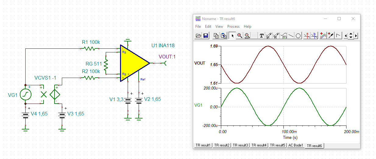
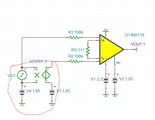
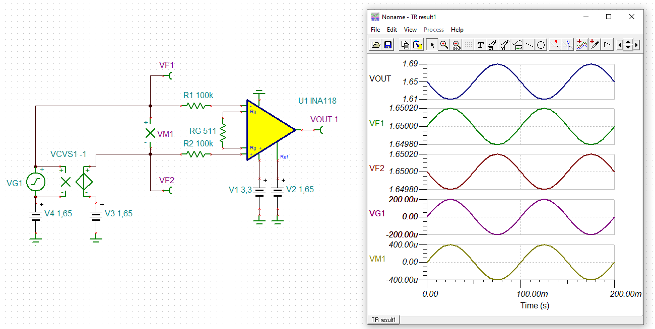
The schematic is shown below:

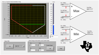
I've used the TI analogue engineers calculator to determine the relationship between VCM and VOUT. As shown below:

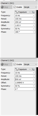
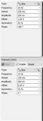
With this considered the amplifier should operate just fine with the following 2 input signals

As you can see below, i've used the signal generators to add an offset to each wave input to act as a common mode input to each signal, they are out of phase so as to create a fully differential signal.

Channel 1 sig gen, is attached to the non-inverting input. Channel 2 sig gen is attached to the inverting input.

HAVE I CONFIGURED THIS CORRECTLY TO GENERATE THE 1.65V VCM & 200uVSIN(wT) VDM?

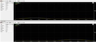
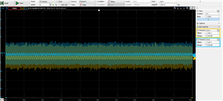
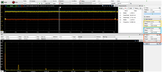
The output is shown below. The yellow trace is the output of the INA118 and the blue trace is attached to the vref pin. The red trace is a simple math channel, not really relevant, but adds some context.

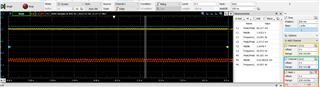
This is a very simple circuit, thus i have 2 very simple questions.

1: Why is the output signal, shown above in yellow, not centered around VREF, the blue trace. Note that if i switch the two input signals, the yellow output trace appears above the blue reference trace instead. Could this be an issue with the Digilent AD2 im using s a signal generator & scope.

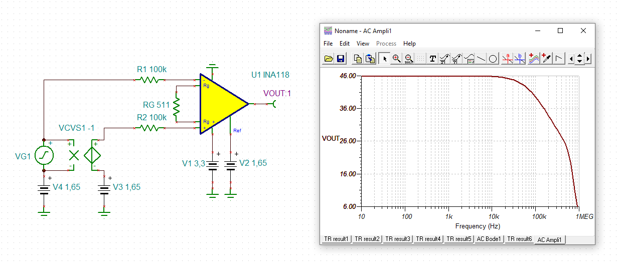
2: Gain appears to be incorrect, as the circuit should have a gain of 100. & I'm seeing no changes in the amplitude of the output signals until the input reaches 300uV (then the output behaves a little more realistically).

I've tried all the obvious things, calibrating probes, swapping the silicon, i do have my doubts about the AD2...

Any thoughts appreciated.

Thanks,

Sean

  • Hi Sean,

    should work:

    sean_ina118.TSC

    Kai

  • Hi Sean,

    Kai is right, this circuit should work. It could be the way you have the circuit connected, the way signals are generated, or the way you are measuring the output. 

    Are you using a specific EVM? What equipment are you using? Can you connect a meter at each input so we can see if you are feeding the correct signal into the circuit? How are you generating the 1.65V reference voltage?

  • Kai,

    Can you please explain to me the exact meaning of the notation on your schematics that i've highlighted below. I'm not familiar with your simulation platform.

    I asked in my original post if i've set up my two waveform generators correctly?

    The configuration for these is below. Does my configuration for my practical implementation, match up with your simulated implentation? Forgive the daft question, I do not have the software platforms available to simulate the circuit and am not familiar with your symbols & notation. Have we both generated an input signal with the same differential and common components?

    Thanks,

    Sean

  • Tamara,

    I'm using a Digilent analogue discovery 2, I have doubts about the device, it was not my first choice of tool

    See below a few screenshots from connecting the sig gen outputs directly to the scope inputs.

    This is with the BNC adapter & high impedance probes attached:

    I'm pumping the below 2 signals, straight into the 2 scope channels, sig gen 1, is attached to the yellow trace, sig gen 2, is attached to the blue trace.

    Notice, for reasons unknown to me, when i select an offset of 1.65V, the waveforms software centers the wave around ~1.645V... regardless, both waves should be exactly the same (apart from phase).

    ...But they are not!.... (quite frustrated to be honest!)... i've tried this before and some how not spotted the problem.

    I've tried swapping the probes around to most of the possible probe combinations, calibrating the probes, i've tried removing the BNC adapter all together, and connecting the sig gen's to the scope inputs of the AD2 device with only flying wires, tried putting the input waves in phase with eachother etc etc ... same results.

    Key question: Could this offset between the two input waves explain the abstract behaviour of the circuit. (see original 2 questions at end of original post)?

  • Hi Guys,

    Thank you both for the replies, slight update here.

    As Tamara has uncovered, there seems to be a slight difference between the DC component of my 2 input signals, NO IDEA WHY! cannot seem to find anything online about this, so i've tried to manually compensate the signal generators to make up for it. but for now, i'll have to live with it.

    So i guess we can assume that part of the DC component of each signal generator has made it into the differential signal. The DC offset if not totally cancelled out? Is this a feasable assumption? Assuming it is, this would explain why the output is not centered aroudn VREF! (Question 1 from my original post...)...Consider question 1 mostly answered.

    So, below i've repeated my ORIGINAL experiment, exactly the same input parameters, except now, i've "manually compensated" for whatever is wrong with the AD2 signal generators.

    As before, yellow is output, blue is VREF. Still not quite centred, but it is CLOSER

    BUT original problem, question 2, still remains, my GAIN appears way too high. Gain should be 100.

    Input amplitude is 200uV, so i should see an output amplitude of 20mV? Yet is is more like 100mV.....

    Thanks again,

    Sean

  • Hi Sean,

    TINA-TI only allows one signal source when performing a AC analysis, so I used a voltage controlled voltage source (VCVS) to generate a duplicated "out of phase" sine:

    The actual differential input signal (VM1) is 400µVp and as the output signal of INA118 is 40mVp, the gain is 40dB (= factor 100). That the earlier gain simulation displays 46dB has to do with the fact, that TINA-TI only considers VG1 and not VG1 plus the duplicated out-of-phase sine.

    Kai

  • Hi Sean,

    reduce the input resistors from 100k to 1k. Does this change the output offset voltage (difference between yellow and blue curve)?

    Then, in a second step, reduce the gain of INA118 from factor 100 to factor 10 and later to factor 1. What do you observe now?

    Kai

  • Hi Sean,

    In addition to the Kai's suggestions, we may even consider trying to simplify this circuit even further by configuring the circuit in dual-supply (+/-3.3V) and grounding the reference voltage and removing the VCM offset from the two input signals. That way we don't have to worry about manual offset calibration at the input. 

  • Hi Tamara,

    yes, that's a good idea Relaxed

    A bipolar supply voltage for the INA118 will also simplify things in the final EEG application.

    Kai

  • Hi Guys, apologies for the delayed reply.

    I will try both of your suggestions over the coming days.

    Wih regards to dual supplies, i'm desperately trying to avoid the use of dual supplies where i can as this will be part of a battery operated application, one with very heavy space constraints, where i cannot simply add a second battery. I did have a quick look into other means of generating a negative supply, if you have any suggestions feel free to voice them. But really, if i can keep to single supply i'd like to.

    It seems as per my previous post, the AD2 waveform generator was the culprit of many of my issues. As i didn't have any other signal generators to hand, not the spare components to throw together an inverting amplifier to make a better differential signal. I decided to skip a few steps and try some real EEG electrodes (without expecting much). I'm actually seeing some reasonable results, i've had to make a few other modifications to get it to "work".

    Still a few issues, but of course, using real EEG signals is far less controlled than generated signals, thus i quite narrow down the issues as of yet. I'll take a look at your suggestions and get back to you. Thanks again,

    Sean